This example shows the input and functionality of the shear force reduction for single loads close to the support, as well as the design at the distance d from the support face using the example of a two-span beam.
System, Loading, and Combinatorics
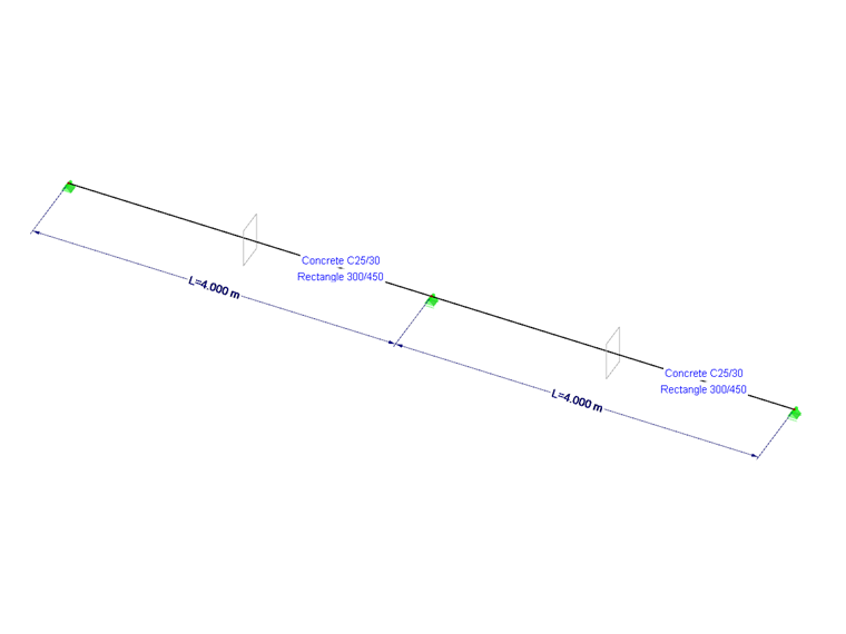
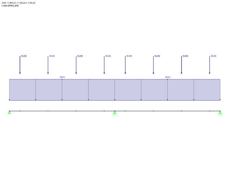
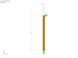
We create a two-span beam with a span length of 4.0 m in RFEM or RSTAB. The rectangular cross-section has the dimensions w/h = 30/45 cm. We select grade C25/30 concrete as the material.
The load for this example results from a permanent and a variable load. The permanent loads are entered in load case 1. This is the self-weight of the cross-section and a line load of gk = 48.75 kN/m. As a variable load, we enter a line load of qk = 37.5 kN/m and, alternatively, a concentrated load introduction as three single loads with Qk = 37.5 kN (member load, concentrated n x P). We enter these two loads separately for the respective field and treat them alternatively in the combinatorics.
In RFEM and RSTAB, the automatic combinatorics are activated to create the load combinations for ULS and SLS. To prevent the alternative load cases from being combined with the distributed or concentrated loads, they are each assigned to a group.
Download the file at the end of this article to see all the other inputs we have made in RFEM and RSTAB.
Shear Force Distribution from RFEM and RSTAB
We can now calculate the internal forces for the two-span beam design in RF-CONCRETE Members or CONCRETE from the previously entered data. For the ULS design, this results in an enveloping RC1, which contains the shear force distribution from both the uniform load and the alternative concentrated loads.
To explain the following entries or the results of the reduction, the calculation does not use the enveloping RC1, but the individual LCs that have either a pure uniform load or a combination of an equal and a single load. In this case, only the cases with a full load (left and right panel loaded simultaneously) are considered. The options described below are not available for the result combination design. See also the notes in the last section of this article.
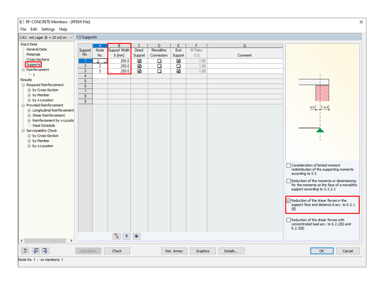
Define Support Width
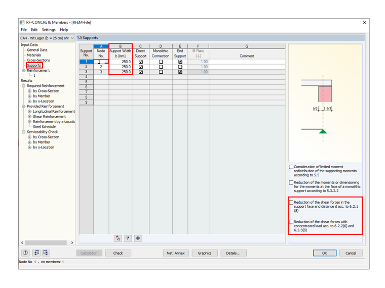
In Window "1.5 Support", you can enter the support width in Column B. Please note that entering the support width without selecting the "Reduction of the shear forces in the support face..." option has no influence on the shear force design.
It is also possible to delete the entire Table 1.5 with the support and node number definitions. However, it may be necessary to specify supports without activating one of the available options for the shear force reduction if a deformation calculation is performed for the serviceability limit state. In this case, you can use the supports to calculate the reference length l0 to determine the maximum deformation limit value. For this purpose, the separate Window "1.7 Deflection Data" is available, where the deformation analysis is activated. You can select the supports defined here. This article does not go into this option further.
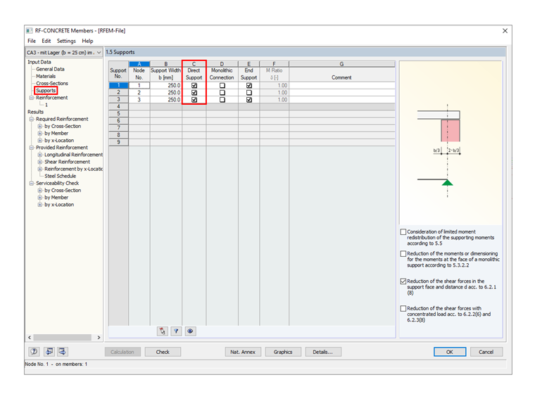
Direct Support
It is necessary to activate the direct support if, according to 6.2.2 (6) or 6.2.3 (8), single loads close to the support are to be reduced with ß = av / 2 d. If there is a secondary beam transferring its load to another beam and not to a "direct support" (column, nodal support, wall, etc.), you should clear this check box in Window 1.5.
Design at the Distance d from the Support Face
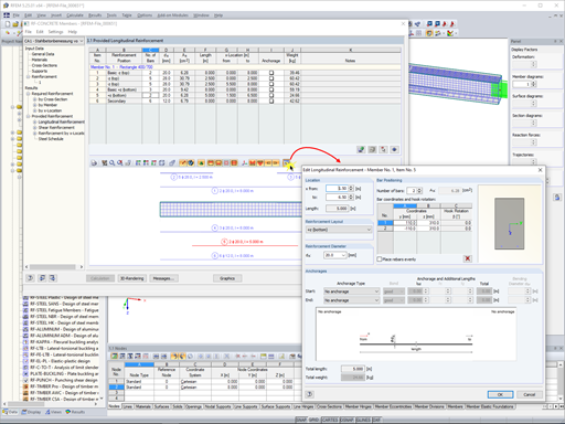
If you have defined the support numbers of the nodal supports correctly in Window 1.5 and also set the support width, you can apply the reduced shear force for the design and determination of the required shear reinforcement with the selected option "Reduction of the shear forces in the support face and distance d according to 6.2.1 (8)".
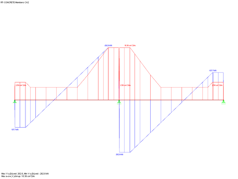
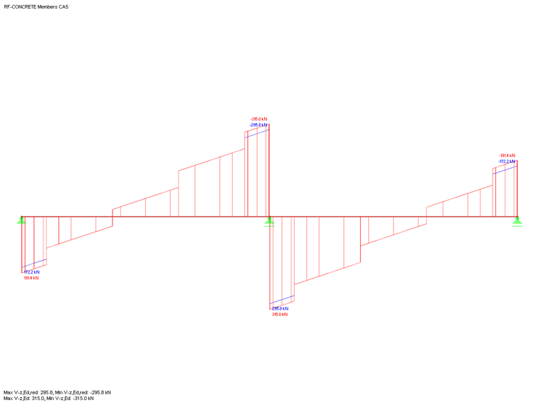
You can see below the shear force distribution Vz,Ed and Vz,Ed,red including the design at the distance d and a defined support width of 25.0 cm.
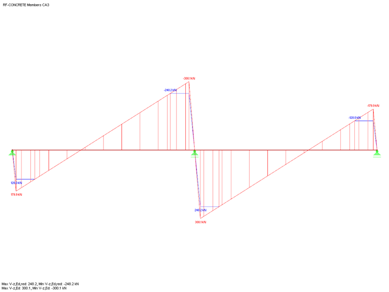
You can see that the shear force at the x-location is set to zero directly above the support. This results from the specification of "Design at distance d". The shear force distribution in the add-on module has a zero crossing at this location. At the perimeter or at the x-location of the support face, the maximum value of the non-reduced shear force is Vz,Ed. The distance d from the support face results in the maximum value of the reduced shear force, Vz,Ed,red.
Reduce Single Loads Close to the Support
To explain the reduction of single loads close to the support, the previously discussed two-span beam is now designed in RF-CONCRETE Members or CONCRETE for a CO with concentrated load application.
By activating the "Direct Support" function described above and the "Reduction of the shear forces with concentrated load according to 6.2.2 (6) and 6.2.3 (8)", single loads in the range of 0.5 d <av <2 d with ß = av/2 d are now reduced. This can be illustrated by comparing Vz,Ed to Vz,Ed,red.
According to 6.2.2 (6), when applying the reduced value Vz,ED,red for the VRd,c design in Equation (6.2a), the applied longitudinal reinforcement (longitudinal reinforcement ratio ρl) must be fully anchored to the support. Furthermore, you have to check the shear force determined without reduction ß with regard to the requirement according to Eq. (6.5).
For structural components with a calculated shear reinforcement according to [1] 6.2.3, the value Vz,Ed must be applied with ß according to 6.2.3 (8) for the design of VRd,max without reducing the individual loads close to the support.
Special Cases of Ribs and Result Combinations
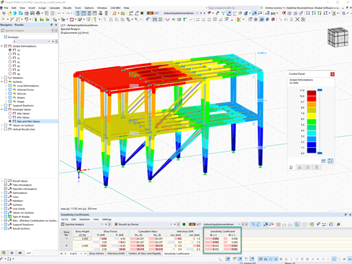
For reduction of the concentrated loads close to the support as well as for the design of the uniformly distributed load at the distance d from the support, the add-on module analyzes the distribution of the shear force Vz from the internal forces of RFEM or RSTAB. With the shear force distribution analysis, the program recognizes a uniformly distributed load from a linear distribution of the shear force and the size of the concentrated loads close to the support from jumps in the shear force distribution.
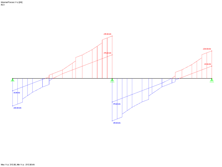
The evaluation of the shear force distribution is, therefore, the basis for the shear force reduction mentioned here. This also results in the restriction that these options are not available for the design with a result combination (RC), since a uniformly distributed load cannot necessarily be assumed for an RC. See also the shear force distribution Vz in Image 03.
The same applies to the design of ribs when utilizing RF-CONCRETE Members. The rib internal forces are partly composed of the member internal forces of the eccentrically connected T-beam and partly of the integrated surface internal forces of the connected plates. Singularities in the surface internal forces can now ensure that the integrated rib internal force (shear force Vz from RFEM) has no linear distribution in the program. Likewise, jumps in the shear force distribution Vz can result from a possible integration of singular surface internal forces. Therefore, the mentioned options to reduce the shear force are not available for rib member design.


.png?mw=600&hash=49b6a289915d28aa461360f7308b092631b1446e)
