Defining Design Supports in RFEM 6
Technical Article
To perform deflection analysis in the right manner, it is important to “inform” the program about the exact support conditions of the element of interest. The definition of design supports in RFEM 6 will be shown for a reinforced concrete member set.
Design Supports of a Reinforced Concrete Member Set in RFEM 6
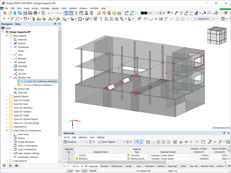
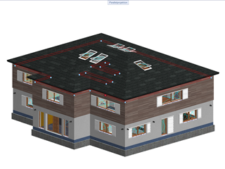
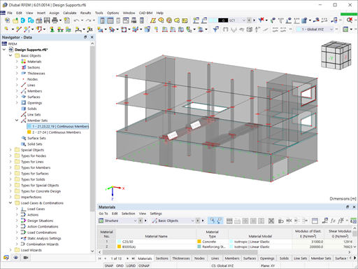
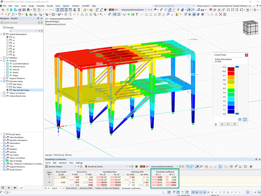
The member set for which design supports will be defined in this example is a reinforced concrete beam belonging to the structure shown in Image 1. The total length of the member set is 13 m and it is placed between two walls. A column is also placed in the middle of the length.
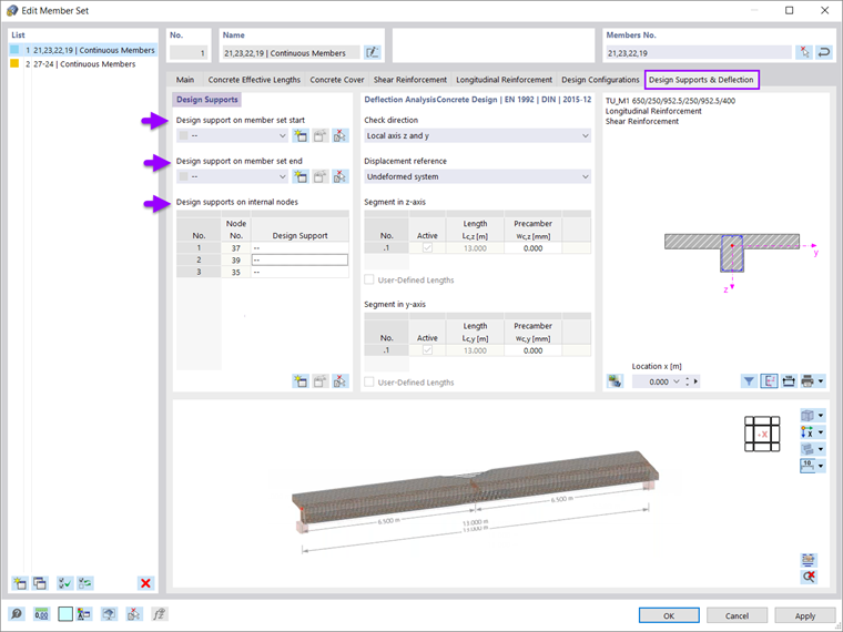
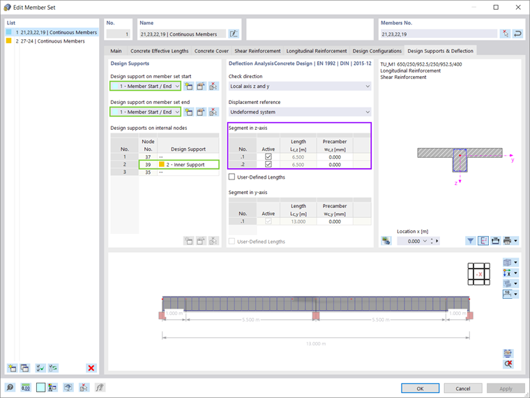
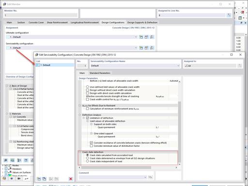
To define the supports for the deflection analysis it is necessary to use the Design Supports & Deflection Tab of the Member Set window. As Image 2 shows, design supports can be defined at member set start, member set end, and internal nodes.
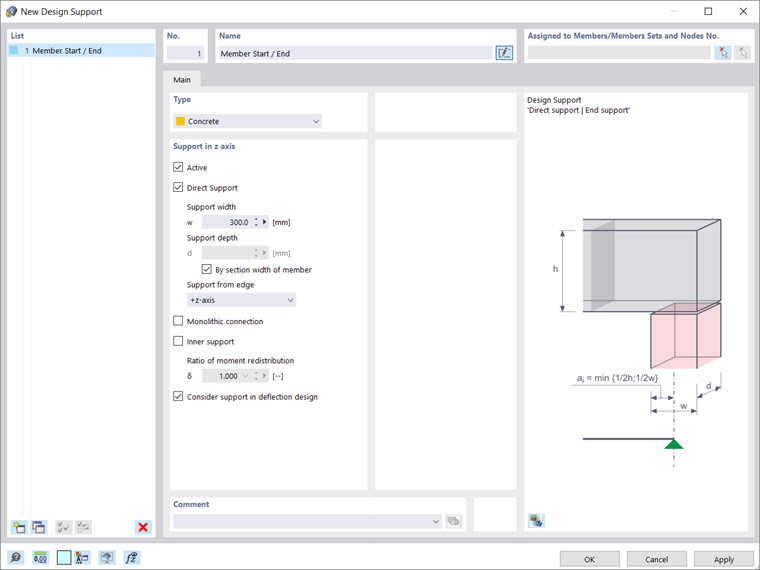
When creating a new design support, it is important to define the type; in this example, the type is Concrete. The support is active and direct. The width and depth of the support can be assigned by the user or taken from the width of the member. If the connection between the member and the support is monolithic, this can also be taken into account by the program. Since the member set of interest is supported by walls at both the start and the end, Image 3 shows the creation of a design support to be defined at these two locations.
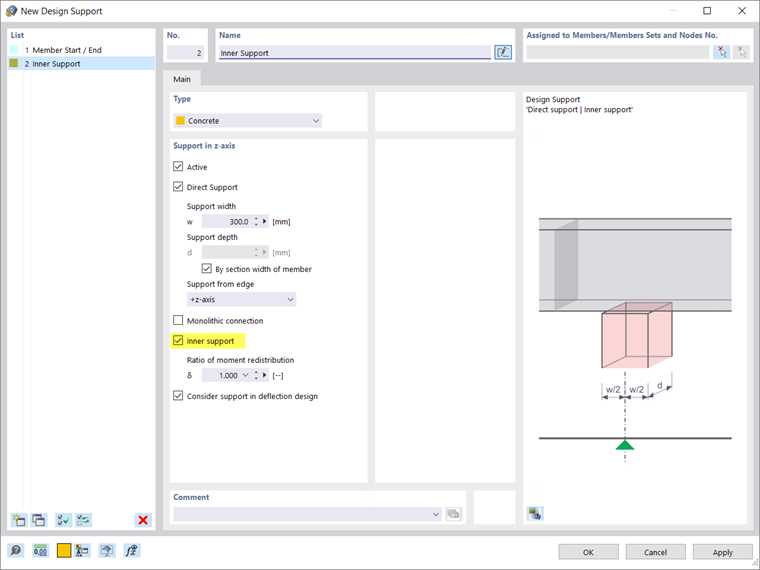
The member set is supported by a reinforced concrete column in the middle of the span; therefore, new design support has to be created (Image 4). The same discussion as for the initially created design support applies here as well. To define this is an inner support, it is important to check the associated check box.
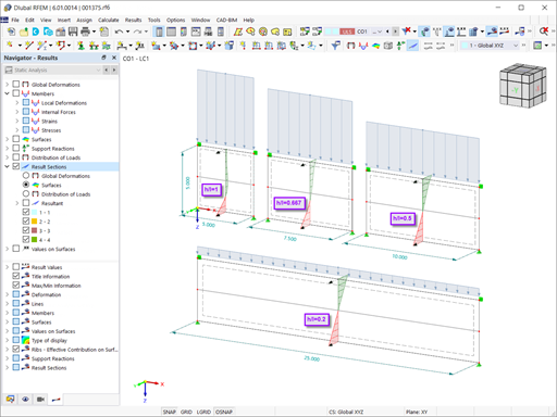
Once the design supports have been defined, they can be assigned on the right location of the member set as shown in Image 5 (i.e., the member start, member end, and the relevant internal node). The assignment of the design supports result in the division of the member set into two spans of 6.5 m. In this manner, the reference length is considered correctly for the deflection analysis.
Author

Irena Kirova, M.Sc.
Marketing & Customer Support
Ms. Kirova is responsible for creating technical articles and provides technical support to the Dlubal customers.
Keywords
Deflection analysis Design supports
Links
- Product Description of "Concrete Design"
- Recorded Webinar | Model and Design Reinforced Concrete Structures in RFEM 6 and RSTAB 9
Write Comment...
Write Comment...
Contact Us
Do you have further questions or need advice? Contact us via phone, email, chat, or forum, or find suggested solutions and useful tips on our FAQ page, available 24/7.

New
Design of Deep Beams in RFEM 6
According to EN 1992-1-1 [1], a beam is a member of which the span is no less than 3 times the overall section depth. Otherwise, the structural element should be considered as a deep beam. The behavior of deep beams (i.e., beams with a span less than 3 times the section depth) is different from the behavior of normal beams (i.e., beams with a span that is 3 times greater than the section depth). However, designing deep beams is often necessary when analyzing the structural components of reinforced concrete structures, since they are used for window and door lintels, upstand and downstand beams, the connection between split-level slabs, and frame systems.

New
Concrete Design | Reinforced Concrete Design with Net Concrete Area
During the cross-section design, you can control whether the concrete surface is applied behind the reinforcing bars or is subtracted from the concrete cross-section. The design of the net concrete cross-section is mainly used for highly reinforced cross-sections.-
In RFEM 6, is it possible to display a graphic with the distribution of the required reinforcement in the DIN A0 format?
- I would like to perform punching design of a floor slab. I have selected nodes for the design, but they are marked as invalid. Where did I make a mistake?
- The limit stress is activated, but my stress ratio is “non-designable” in the Stress-Strain Analysis add-on. What could be the reason?
- How do I define a member as a cantilever and not as supported at both ends for serviceability or deflection design?
- Where can I find the graphical results of punching shear in the concrete design? Especially the distribution of shear forces at the critical perimeter or the punching loads.
-
Is it possible to display the reinforcement description in RFEM 6?
- I would like to export nodal support forces of several load cases, load combinations and result combinations into an Excel spreadsheet in RFEM 6. How should I proceed?
- Where can find the option to hide the defined types (for example, design supports or effective lengths)?
- How do I create a user-defined Design Situation with my own chosen load combinations?
- Can I define a different bar size in the RFEM 6 Concrete Design add-on other than the default bar sizes available in the drop-down?
- I would like to export nodal support forces of several load cases, load combinations and result combinations into an Excel spreadsheet in RFEM 6. How should I proceed?
Associated Products