Control Perimeter
The punching shear check first calculates the Critical Section Area (Asection), which is the surrounding area of the node of punching. According to ACI 318-19 Sec. 22.6.4 [1] and CSA A23.3:19 Clause 13.3.3 [2], the critical perimeter (bo) for a square column is equal to the perimeter length of the concentrated load or reaction area that is no closer than half the distance of the effective depth (d). Asection and bo are both automatically calculated by RFEM based on the location of the concentrated loading on the slab.
Punching Design Parameters in RFEM 6
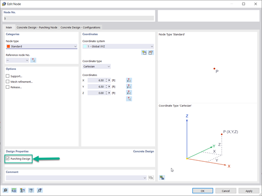
Once the Concrete Design add-on has been activated, the Punching Design Properties check box will appear in the Main tab when editing the punching shear node in RFEM 6. This can be done simultaneously for all nodes in which punching shear is a concern. In the Input Data of the Concrete Design add-on, the nodes being designed for punching shear must also be selected.
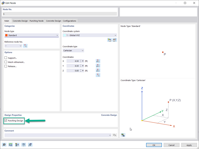
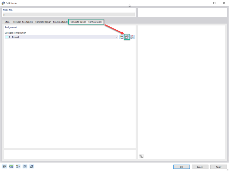
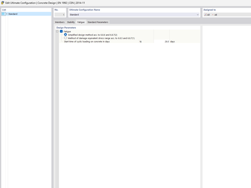
Once Punching Shear Design Parameters is checked on a for a node, the Concrete Design - Punching Node and Concrete Design - Configurations tabs will appear. This allows you to change options regarding the Punching Reinforcement Type, Placement, Rebar diameter, and Material. The Ultimate Configurations tab will appear with further design parameters that can be adjusted by the user such as "single" or "smoothed" forces for columns/walls and minimum reinforcement spacing. The Strength Reduction factors acc. to ACI 318-19 Sec. 21.2.1 [1] and CSA A23.3:19 Clause 8.4 [2] can be adjusted along with the minimum spacing of reinforcement.
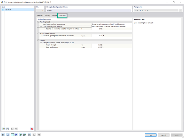
Within the critical perimeter, the shear force from the Punching Load for walls is set to smoothed. Whereas for columns, the punching load can either be set to "smoothed" or "single force" from the column, load, or nodal support.
Punching Shear Design in RFEM 6
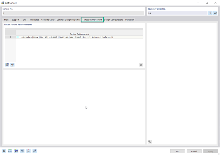
Once the design parameters for punching shear and reinforcement are entered under the node and the surface, the design is performed by the Concrete Design add-on. The design references the longitudinal reinforcement shown in the next image. Once the concrete design is executed considering only this reinforcement, the design ratios will be shown for all nodes of interest and are available in table form or graphically.
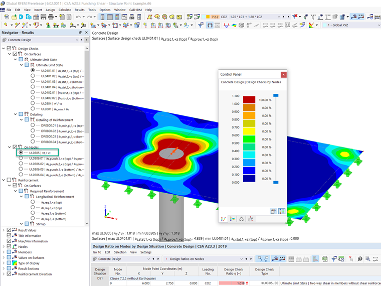
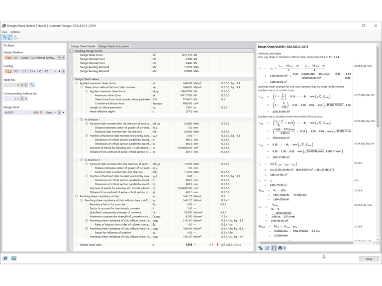
In the results, the Punching Shear Resistance of the Slab (vn) and the Applied Maximum Shear Force (vu) are compared to each other to calculate the overall design ratio according to ACI 318-19 Sec. 22.6.1.2, Eq. (22.6.1.2) [1]. Similarly, the Punching Shear Resistance of the Slab (vr) and the Applied Maximum Shear Stress (vf) are used to calculate the design ratio according to CSA A23.319, Clause 13.3.4 [2]. These equations can be found in the Design Check Details shown in Image 7 along with the entire calculation procedure.
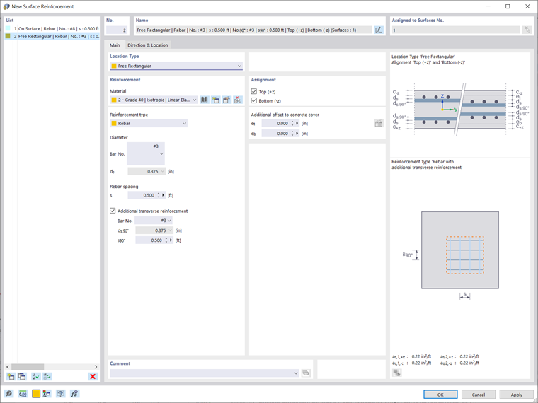
If no additional punching shear reinforcement is added and Vu≤ Vn, then no additional reinforcement is required. On the tension side of the slab, additional local longitudinal reinforcement can be added if the resistance is exceeded by the applied shear. For this example slab, you can see this can be done by defining a Free Rectangular Region on the top of the location where the column is framing in. This reinforcement definition can be copied and pasted to all punching nodes using the "copy/move" tool. The reinforcement assigned in this way will be considered automatically when calculating the shear capacity.
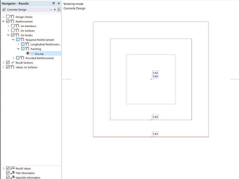
The results, again, can be found in the Concrete Design table or viewed graphically. In terms of the amount of punching required reinforcement, this can be displayed in the Results tab of the Navigator (image below).
Conclusion
In RFEM 6, the Punching Design check can be initialized within the Edit Window of a node and is then automatically considered in the Concrete Design add-on. Then, the activation of the design properties will allow the punching design parameters to be manipulated, such as the Punching Load, Strength Reduction factors according to ACI 318-19 Sec. 21.2.1 [1] and CSA A23.3:19 Clause 8.4 [2], and the minimum spacing of reinforcement under the Ultimate Configuration settings. The concrete design is performed on the basis of the longitudinal reinforcement provided from the surface. If the design ratio is above 1.00, additional longitudinal reinforcement can be assigned on the tension side of the slab.