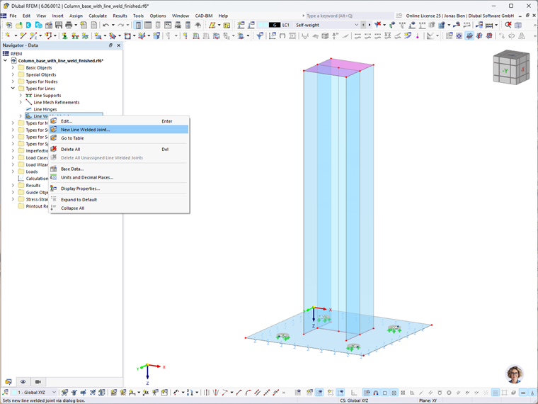
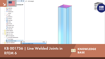
Line welded joints can be defined via the Dialog Box "New Line Welded Joint", as shown in Image 2. The selection of joint type is important for the definition of a line welded joint. There are several types available in the program: butt joint, corner joint, lap joint, and tee joint. Please note that it is also necessary to define a weld type. The list offers different options for performing weld designs depending on the joint type.
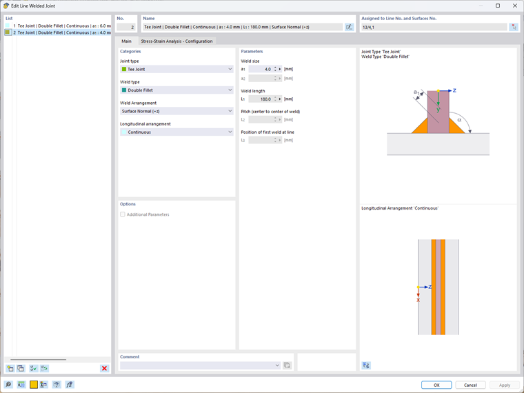
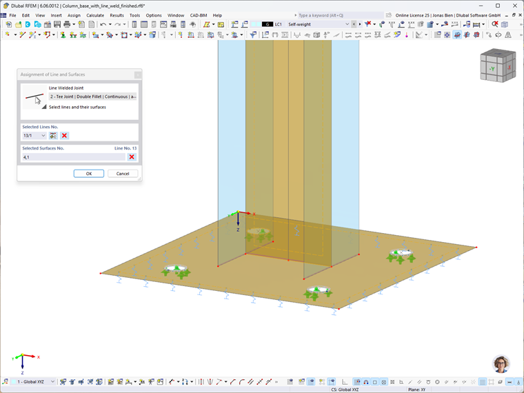
Line welded joints can be arranged “Continuously” over the entire line length. Thus, when you enter the weld parameters, you must assign the “Weld size” to define the weld thickness, whereas the “Weld length” is taken from the line length. The line welded joints can be assigned to lines and surfaces by assigning the number of the line and surface in the upper right corner of the dialog box, or by selecting the joints graphically in the working window. When doing the latter, please note that the order in which the surfaces are selected is important.
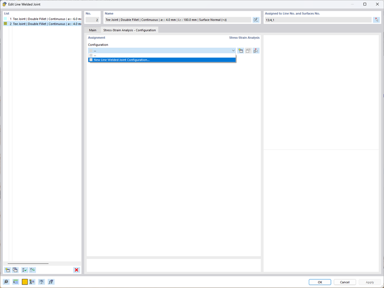
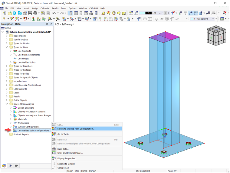
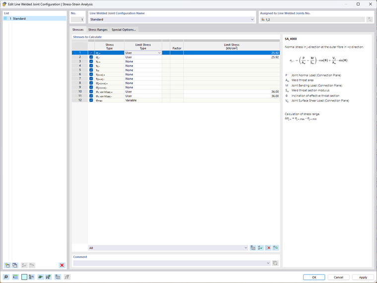
Once you create and assign the line welded joints, you can make basic specifications regarding the line weld joint analysis. This can be done via the Stress-Strain Analysis – Configuration tab of the same dialog box (Image 4), or via the Stress-Strain Analysis entry in the navigator (Image 5).
First, you can select the stresses to be calculated. For instance, you can calculate weld throat stress due to normal load, bending, surface shear load, weld shear load, normal stress perpendicular to the connection plane, resulting weld throat stress, and so on. You can define the limit stress type and the value of the limit stress.
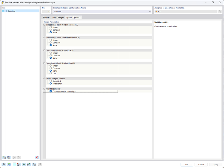
Special options are also available in this dialog box. For instance, you can control the smoothing of the stresses (that is, the distribution of the local stress peaks over the weld seam length) and the stress distribution for fillet welds. For fillet welds, the stress distribution can be determined on the basis of the simplified method according to EN 1993-1-8 4.5.3.3 or the directional method according to 4.5.3.2. It is also possible to consider weld eccentricities. This way, it is possible to consider additional moments that can occur, for example, in the case of one-sided fillet weld structures.
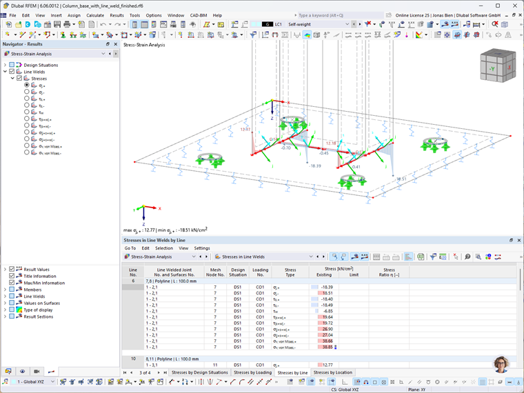
Once the calculation is done, the stresses in the line welds are available in both graphical and tabular form. The navigator allows you to control which stresses will be graphically displayed, whereas the table provides an overview of the stresses by design situations, loading, line, and location.


.png?mw=600&hash=49b6a289915d28aa461360f7308b092631b1446e)


