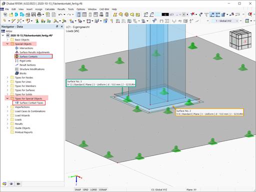
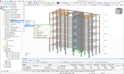
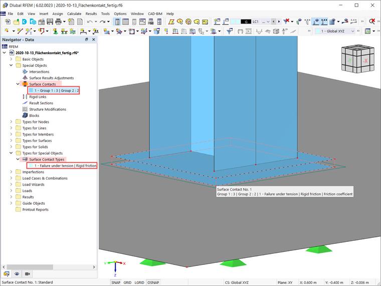
Both surface contacts and the type of surface contacts can be defined via the associated entries in the Data navigator. The former are organized in “Special Objects”, the latter in “Types for Special Objects”. More about their definition will be shown in the example in Image 1 by creating a connection between Surface No. 2 and Surface No. 3.

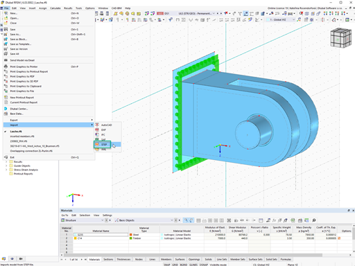
The “New Surface Contact” dialog box is shown in Image 2. As shown, the procedure to define it is fairly straightforward. What you must do first is to enter the numbers of the surfaces between which the contact is being created. Thus, define one of the surfaces as “Group 1” and the parallel surface as “Group 2”.
You can also use the “Select Individually” button to select the surfaces graphically. Please be aware that each group may also consist of several surfaces. These surface groups do not have to lie exactly on top of each other, and they must not lie in the same plane.
Once the surfaces of interest have been selected, you are asked to assign the surface contact type. If one already exists, you can select it from the list. Otherwise, you can define a new one by opening the associated dialog box via the “Create New Contact Surface Type” icon (Image 2). The dialog box for defining a new surface contact type is also available via the “Surface Contact Type” entry in the Data navigator (shown in Image 1).
Hence, you can define the contact type while defining the contact itself (as in Image 2), or you can do it beforehand, then select it from the list in the “New Surface Contact” dialog box. The latter approach is shown in the video of this Knowledge Base article.
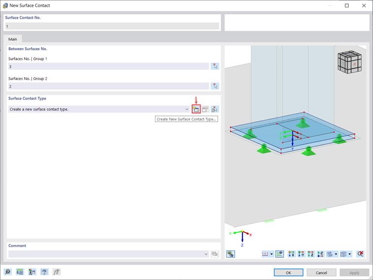
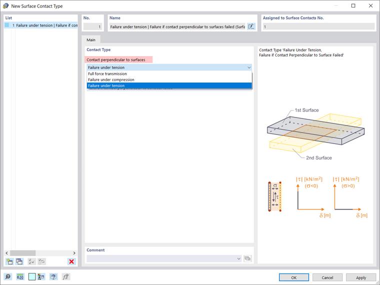
Both approaches lead to the definition of the contact surface types as shown in Image 3. Given that the surface contact type controls the forces that are transferred between the surfaces, it is necessary first to set the contact properties perpendicular and parallel to the surfaces.
In the “Contact perpendicular to surfaces” list, you can select one of the following three options: full force transmission (that is, transfer of both tensile and compressive forces between the surfaces); failure under tension (that is, the contact is released as soon as the surfaces move away from each other); and failure under compression (that is, only tensile forces are transferred between the surfaces).
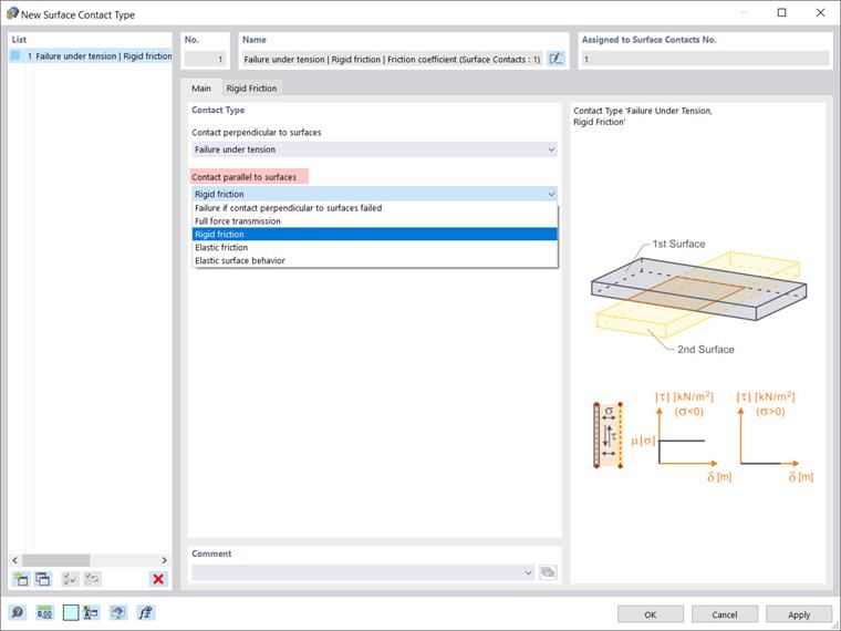
In the “Contact parallel to surfaces” list, on the other hand, there are five options that help you describe how shear forces are transferred between the surfaces (Image 4). You can define, for instance, that no shear forces are transferred if there is no tension or compression contact between the surfaces by selecting “Failure if contact perpendicular to surfaces failed”.
You can also choose “Full force transmission” and all shear forces will be transferred, regardless of whether the contact is effective perpendicular to the surfaces. The other three options at your disposal are: rigid friction, elastic friction, and elastic surface behavior.
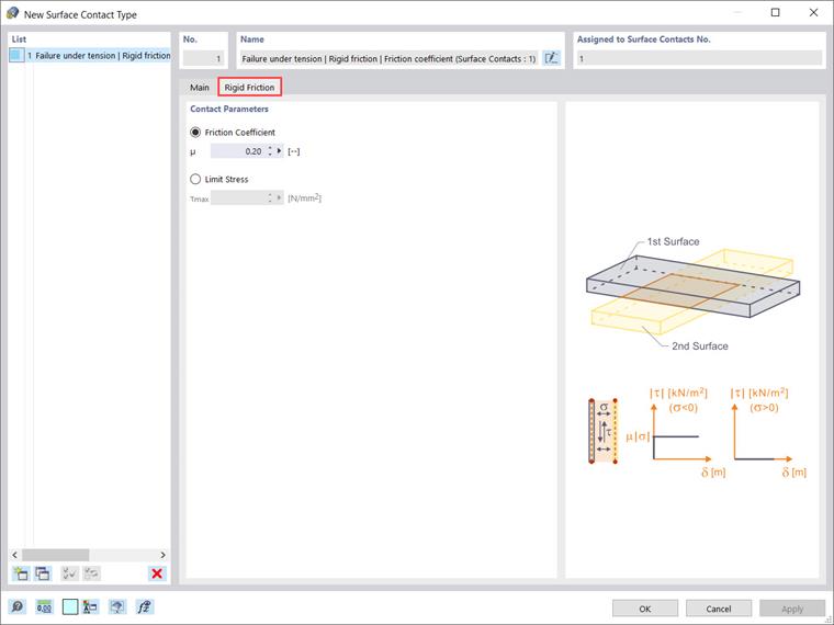
For the sake of completeness, we will show which parameters are to be defined when choosing one of the last three options. Thus, if you select “Rigid friction” in the “Contact parallel to surfaces” list, you must define the friction coefficient μ or the limit stress τmax as contact parameters (Image 5). The friction coefficient μ is associated to the ratio of shear stresses τ (τ = μ ⋅ |σ|), whereas τmax is a limit stress; once it is reached, the stress is not increased further by increasing the deformation, but remains constant.
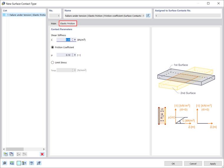
In a similar manner, you can select “Elastic friction” and define the parameters of the contact parallel to the surfaces for which the shear force increases proportionally to the deformation (Image 6). The entry is similar to the one for the rigid friction shown in Image 5. Since an elastic behavior is represented, it is also necessary to specify the constant of the shear stiffness C, which represents the force required to move an area of 1 m2 by 1 m.
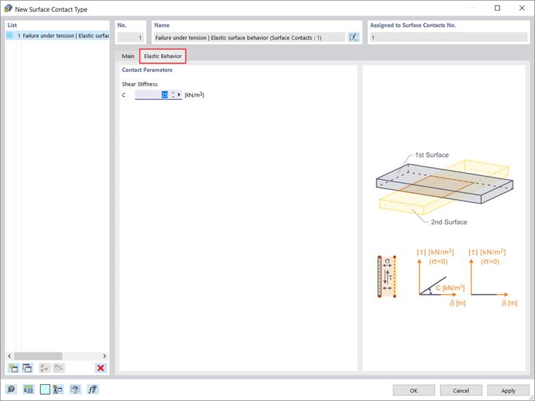
Finally, you can choose an elastic surface behavior and specify the shear stiffness C of the spring in the “Elastic Behavior” tab in order to describe the property of the elastic transfer of shear forces (Image 7).
In this particular example, where the contact between Surface No. 2 and Surface No. 3 is to be defined, “Failure under tension” is chosen to describe the contact perpendicular to surfaces, and “Rigid friction” is selected to describe the contact parallel to them. In this way, the surface contact is defined and shown in Image 8.
Summary
A surface contact describes the connection between two or more parallel surfaces. To define a surface contact, the surfaces of interest must be selected, and the contact properties must be defined. The contact properties are defined by defining a surface contact type which, in fact, controls the transfer of forces between the specified surfaces. Both “Surface Contacts” and “Type for Surfaces” contacts can be defined via the associated entries in the Data navigator.