In RFEM 6, line hinges can be defined using the “Insert” menu. They are also available as “Types for Lines” in the Data navigator. The basic parameters and definition of line hinges are described in detail in Knowledge Base article “Line Hinges in RFEM 6”.
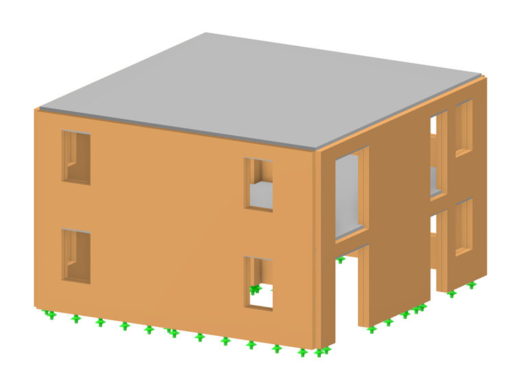
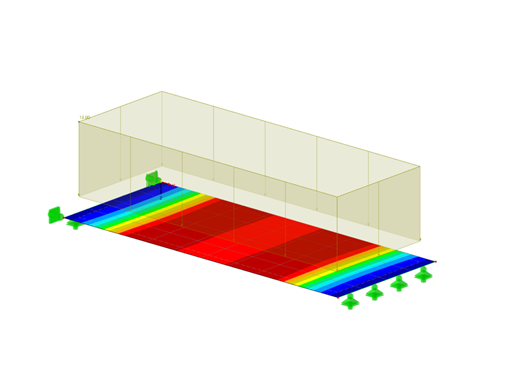
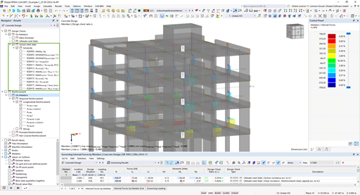
Provided that the line hinge that represents the connection between a reinforced concrete slab and a masonry wall is not a common line hinge, but a special one, the defined parameters differ from those described in the above-mentioned article. The following article will show you the definition of a “slab-wall connection” using line hinges for the connection between the slabs and the exterior walls of the structure shown in Image 1.
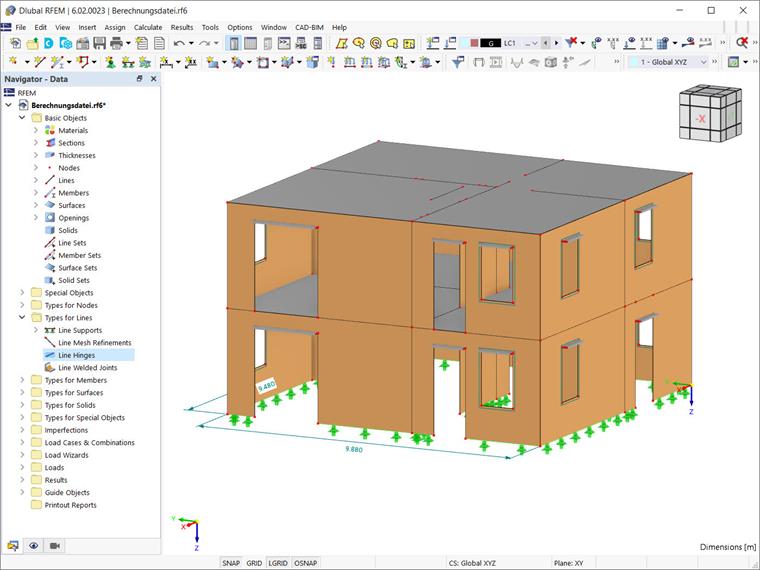
Once you open the “New Line Hinge” dialog box via the “Insert” menu or the “Line Hinges” entry in the navigator, the “Slab-wall connection” option becomes available in the “Options” section (Image 2). By activating this option, you will be able to control the parameters of the line hinge in order to limit the transmission of moments. This can be done in the “Slab-Wall Connection” tab that is available as soon as you select the corresponding check box.
The parameters of a line hinge that represents the connection between a reinforced concrete slab and a masonry wall are (represented by) an “Offset” and a “Block width”. These parameters are also shown in Image 2, and their values are required to determine the correct hinge stiffness within the program.
As mentioned previously, the program allows you to automatically determine the correct stiffness of your wall-slab hinge, based on the interaction diagrams representing various geometric situations. To do so, activate the “Masonry Design” add-on and assign the respective surfaces and lines using the “Select Surfaces/Lines” button in the upper right corner of the “New Line Hinge” dialog box (Image 2).
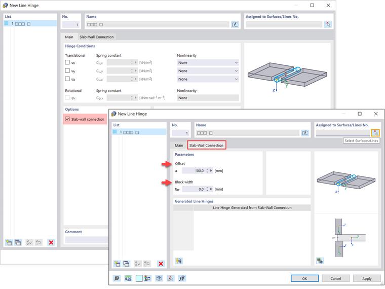
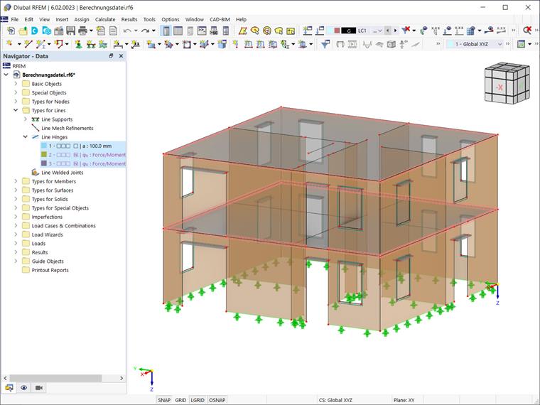
This allows you to select surfaces and lines in the RFEM working window, as shown in Image 3. Please note that you can select several surfaces and lines, as in this example, where the slabs (that is, Surface 10 and Surface 5) and the slab-wall boundary lines are selected at once.
Next, click the “Regenerates line hinges for walls attached to the slabs of this hinge” button at the bottom of the dialog box section (Image 4) to generate line hinges from the slab-wall connection and to show them in the “Generated Line Hinges” section of the “Slab-Wall Connection” tab. The generated line hinges will also be available in the list of line hinges (Image 4).
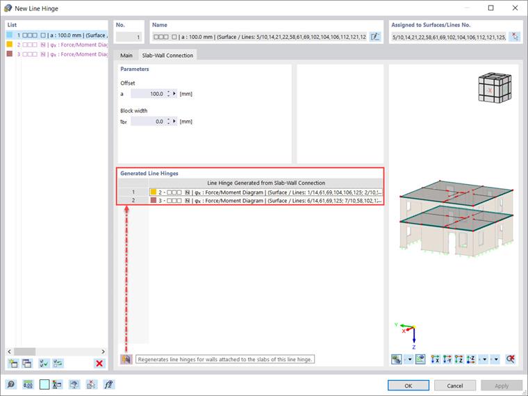
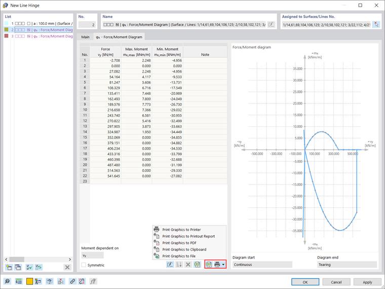
Please note that the generated line hinges are displayed in different colors; the reason for this is the fact that they are created as new types, which cannot be edited. However, the determined diagrams can be displayed as shown in Image 5, as well as printed out and/or exported to a spreadsheet, printout report, PDF, or file.
Finally, the generated slab-wall connections are available, as shown in Image 6.
Summary
RFEM 6 provides you with a special line hinge to model the connection between reinforced concrete slabs and masonry walls. All you have to do is to define the geometry, and the program helps you to limit the transferable forces of the connection depending on it. This is possible based on the interaction diagrams, which are applied automatically and used to determine the correct stiffnesses.