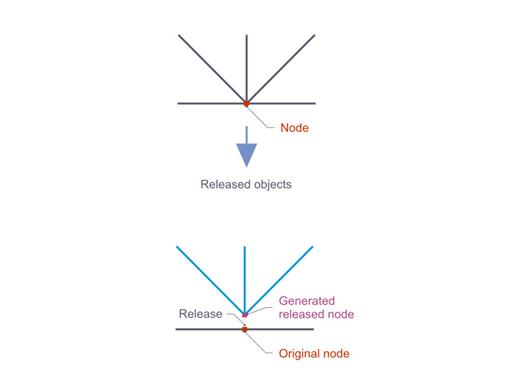
Once the nodal releases are defined, the program generates nodes which belong to different parts of the model and generates an invisible member between these nodes. The internal forces are the same as for a member with the start in the original node and end in the decoupled node.

Nodal releases are mostly suitable for member models with nonlinear geometry. For instance, nodal releases can be used to model member crossings with lifting beams, movable substructures, or coupled objects with special boundary conditions.
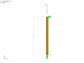
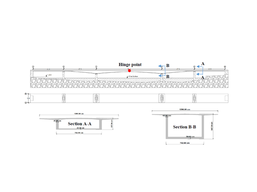
Thus, one case when it is necessary to use nodal releases is in models where one beam lies on top of another but they are not rigidly connected by screwing or welding. An example for this is the beam crossing shown in Image 2 where a cantilever beam lies loosely on a downstand beam.
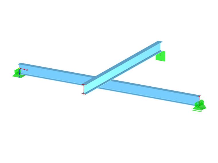
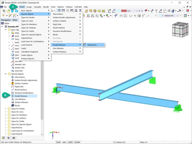
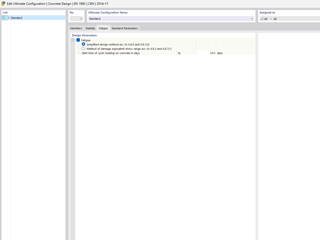
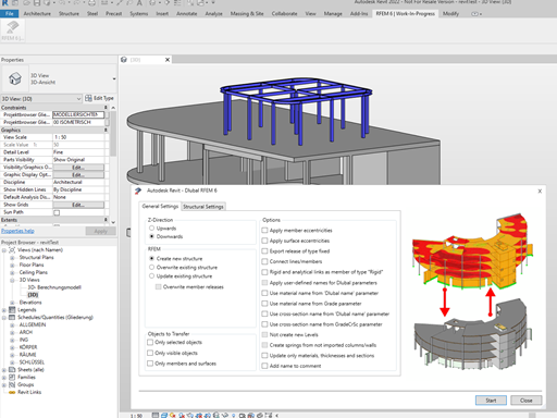
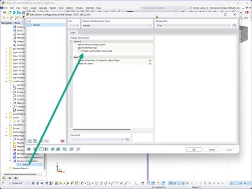
In this case, it is necessary to define a nodal release in order to decouple the model at the location where the beams cross each other. In RFEM 6, you can find the nodal releases under “Special Objects” in the navigator’s data, or by using the menu "Insert" → "Special Objects" → "Nodal Releases" → "Dialog Box" (Image 3).
In both cases, the dialog box "New Nodal Release" is available to you as shown in Image 4. You can start defining the nodal release by selecting the location (that is, the node) at which the model should be decoupled and the nodal release to be generated. This can be done in the upper right corner of the dialog box. Then, in the “Released Objects” section, you must specify the members, surfaces, or solids that are decoupled at the selected node. You can do this by writing their number or by using the “Select Individually” button to define the objects graphically in the work window.
In this particular example, members 3 and 4 (that is, the cantilever beam on the top) are selected for decoupling. In this way, RFEM will generate a copy of the selected node at the same location. In the list available in the “Release Generation” section, you should specify whether to place the release (hinge) on the “Original node” or the “Released node”. The setting specifies with which part of the model the hinge is deforming, thus having an effect on the results.
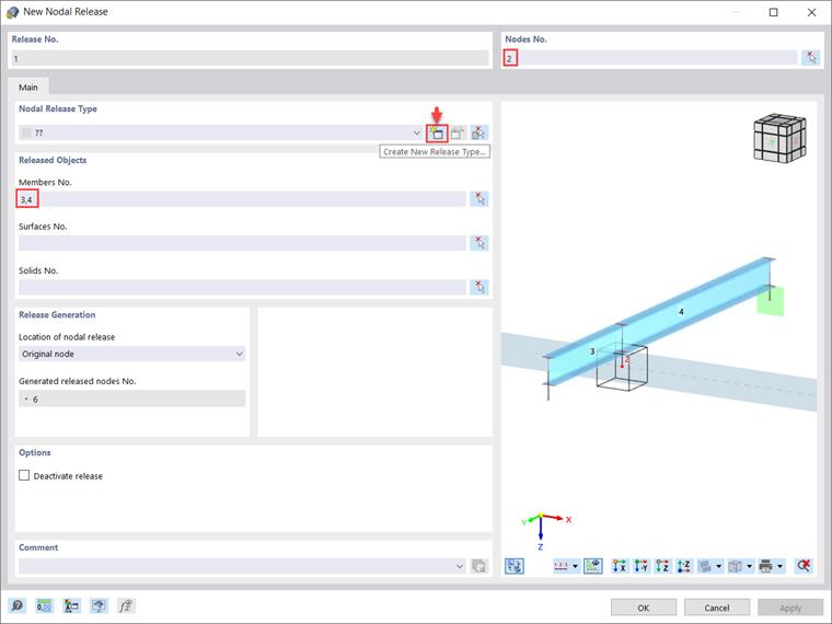
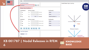
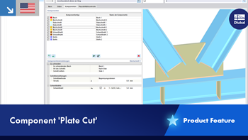
Next, you must define the appropriate conditions for the nodal release. The degrees of freedom on the node are controlled by the nodal release type (Image 5) that describes the properties of the hinge. These properties control the transfer of deformations (and thus of internal forces and moments) between the original node and its copy. A nodal release type can be defined in the associated dialog box accessible via the “Create New Release Type” icon indicated in Image 4, or via the “Types for Nodal Releases” entry in the “Types for Special Objects” of the navigator’s data.
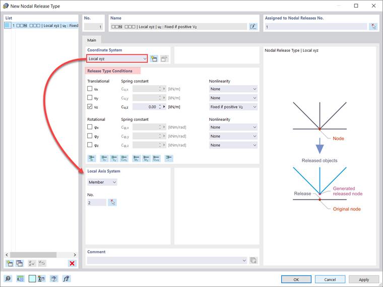
As Image 5 shows, the release type conditions are divided into three “Translational” degrees of freedom and one “Rotational” release. The release properties refer to the axes of members or lines. By selecting the check box for the respective axis, you specify that a displacement in or a rotation about the corresponding direction is possible. Then, you can adjust the constant of the translational or rotational spring and enter the nonlinear properties (if applicable) in the “Nonlinearity” column.
Before confirming the creation of the nodal release type, please verify to which axis system the release of the displacements and rotations are related. This can be specified in the “Coordinate System” section of the “Nodal Release Type” dialog box where you can select one of the following axis systems: local axis system (x,y,z), global coordinate system (X,Y,Z), or you can define a new coordinate system by yourself.
If the release refers to a local coordinate system, the “Local Axis System” dialog section is also displayed (Image 5) and you can define the member or line (depending on what you have selected in the list) that serves as a reference.
Summary
The definition of nodal releases is particularly suitable for member models with nonlinear geometry. In RFEM 6, you can find them as “Special objects” and use them to model member crossings with lifting beams, movable substructures, or coupled objects with special boundary conditions. By defining a nodal release, structural decoupling of the objects connected to a node is allowed. The release is controlled by hinge conditions, which may also have nonlinear properties.


.png?mw=600&hash=49b6a289915d28aa461360f7308b092631b1446e)


