- Design of moment resistant and simple joints of I-shaped rolled cross-sections according to Eurocode 3:
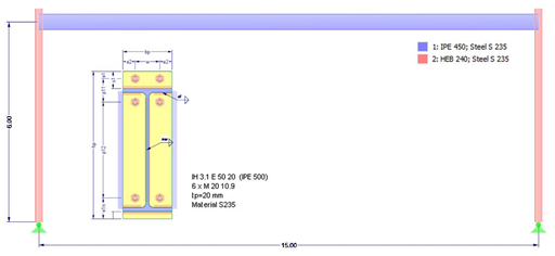
- Moment-resisting end plate connections (type IH/IM)
- Moment resistant purlin splices (PM type)
- Simple joints with angle cleat and long angles (IW and IG types)
- Simple joints with header end plates mounted either on web only or on web and flange (IS type)
- Check of coped connections (IK) in combination with pinned end plates (IS) and angle connections (IW)
- Automatic design of required joint with bolt sizes (all types)
- Check of required thickness of load-bearing members for shear connections
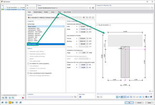
- Results of all required structural details such as appliances, hole arrangements, necessary extensions, a number of bolts, end plate dimensions, and welds
- Results including stiffnesses Sj,ini of bending-resistant connections
- Documentation of available loading and comparison with resistances
- Results of design ratio for each individual joint
- Automatic determination of governing internal forces for several load cases and connection nodes
Features
.png?mw=1024&hash=aa4742c14b9bec5915cecf9750b61376a4ba1153)
Do you have any questions?


Length: 00:00:31 min

Length: 00:00:36 min

Length: 00:00:00 min

Length: 00:50:32 min

Length: 00:00:00 min
Length: 00:00:32 min
Length: 00:00:53 min


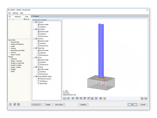
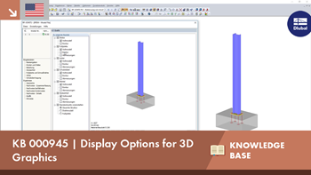
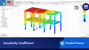
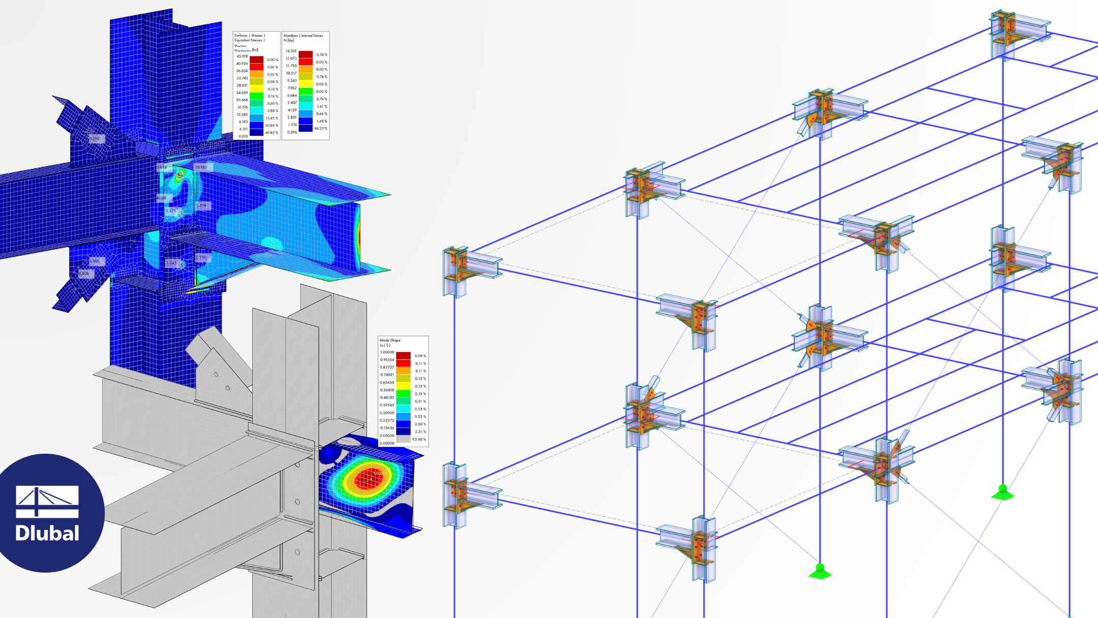
In addition to the result tables, you can create three-dimensional graphics in RF‑/FRAME‑JOINT Pro and RF‑/JOINTS. This is a realistic representation of a connection to scale.
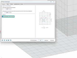
This article deals with the stiffness of standardized joints according to the DSTV (German Steel Construction Association)/DASt (German Committee for Structural Steelwork) standards, often used in steel construction, and its effects on structural analysis and design results according to DIN EN 1993-1-1.

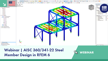
The three types of moment frames (Ordinary, Intermediate, Special) are available in the Steel Design add-on of RFEM 6. The seismic design result according to AISC 341-22 is categorized into two sections: member requirements and connection requirements.

The Steel Design add-on in RFEM 6 now offers the ability to perform seismic design according to AISC 341-16 and AISC 341-22. Five types of seismic force-resisting systems (SFRS) are currently available.
.png?mw=350&hash=4e46efe096ec179df1a2e0dbbb1c27da445328c9)


.png?mw=350&hash=b2324c4db119938012b5490afaa56e9aa826cdcc)

.png?mw=512&hash=946cd2867d0701e2a5a72de20f45b351b3ea8f93)
- Design of moment resistant and simple joints of I-shaped rolled cross-sections according to Eurocode 3:
- Moment-resisting end plate connections (type IH/IM)
- Moment resistant purlin splices (PM type)
- Simple joints with angle cleat and long angles (IW and IG types)
- Simple joints with header end plates mounted either on web only or on web and flange (IS type)
- Check of coped connections (IK) in combination with pinned end plates (IS) and angle connections (IW)
- Automatic design of required joint with bolt sizes (all types)
- Check of required thickness of load-bearing members for shear connections
- Results of all required structural details such as appliances, hole arrangements, necessary extensions, a number of bolts, end plate dimensions, and welds
- Results including stiffnesses Sj,ini of bending-resistant connections
- Documentation of available loading and comparison with resistances
- Results of design ratio for each individual joint
- Automatic determination of governing internal forces for several load cases and connection nodes

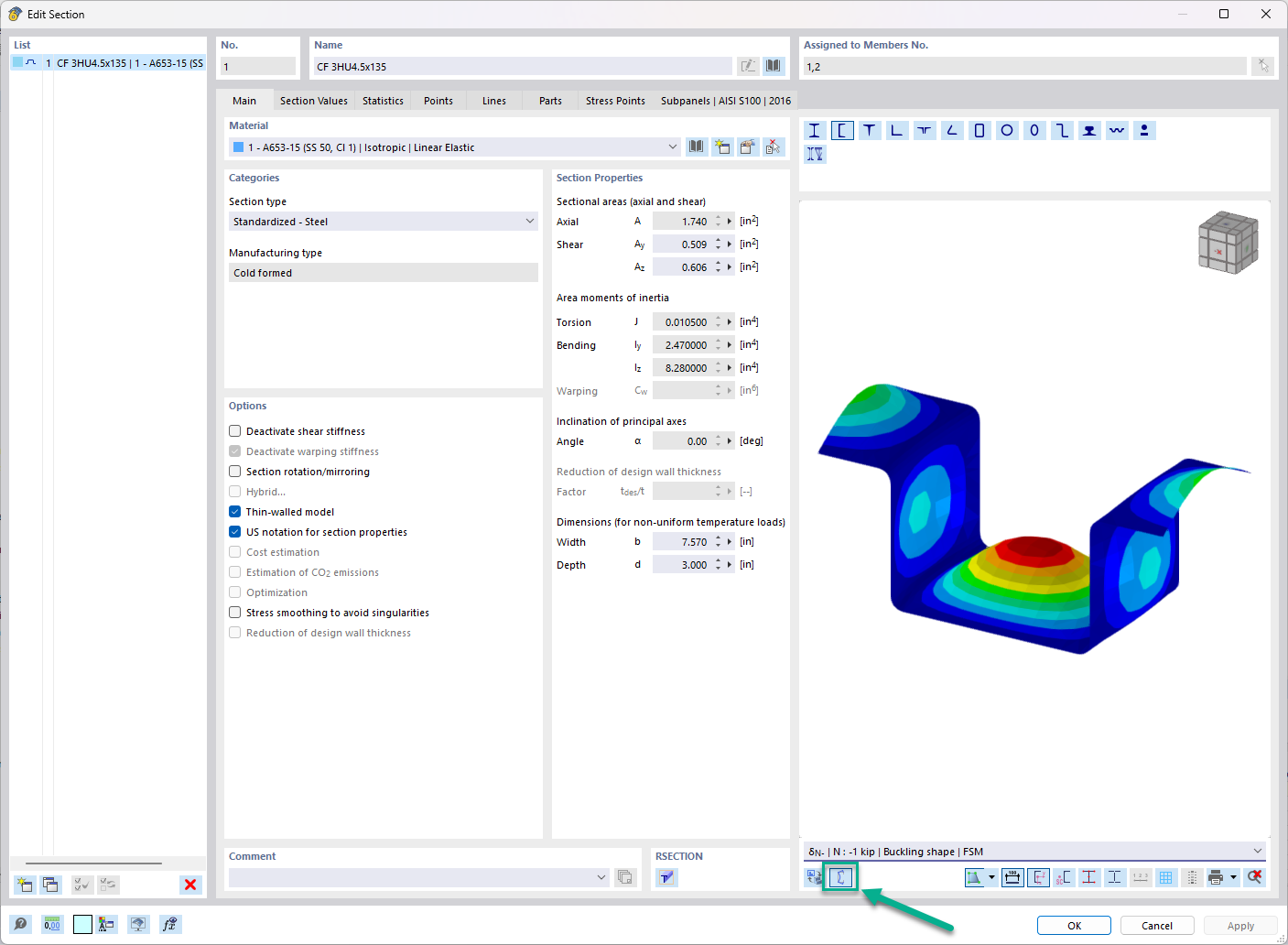
In the "Edit Section" dialog box, you can display the buckling shapes of the Finite Strip Method (FSM) as a 3D graphic.

- Design of five types of seismic force-resisting systems (SFRS) includes Special Moment Frame (SMF), Intermediate Moment Frame (IMF), Ordinary Moment Frame (OMF), Ordinary Concentrically Braced Frame (OCBF), and Special Concentrically Braced Frame (SCBF)
- Ductility check of the width-to thickness ratios for webs and flanges
- Calculation of the required strength and stiffness for stability bracing of beams
- Calculation of the maximum spacing for stability bracing of beams
- Calculation of the required strength at hinge locations for stability bracing of beams
- Calculation of the column required strength with the option to neglect all bending moments, shear, and torsion for overstrength limit state
- Design check of column and brace slenderness ratios

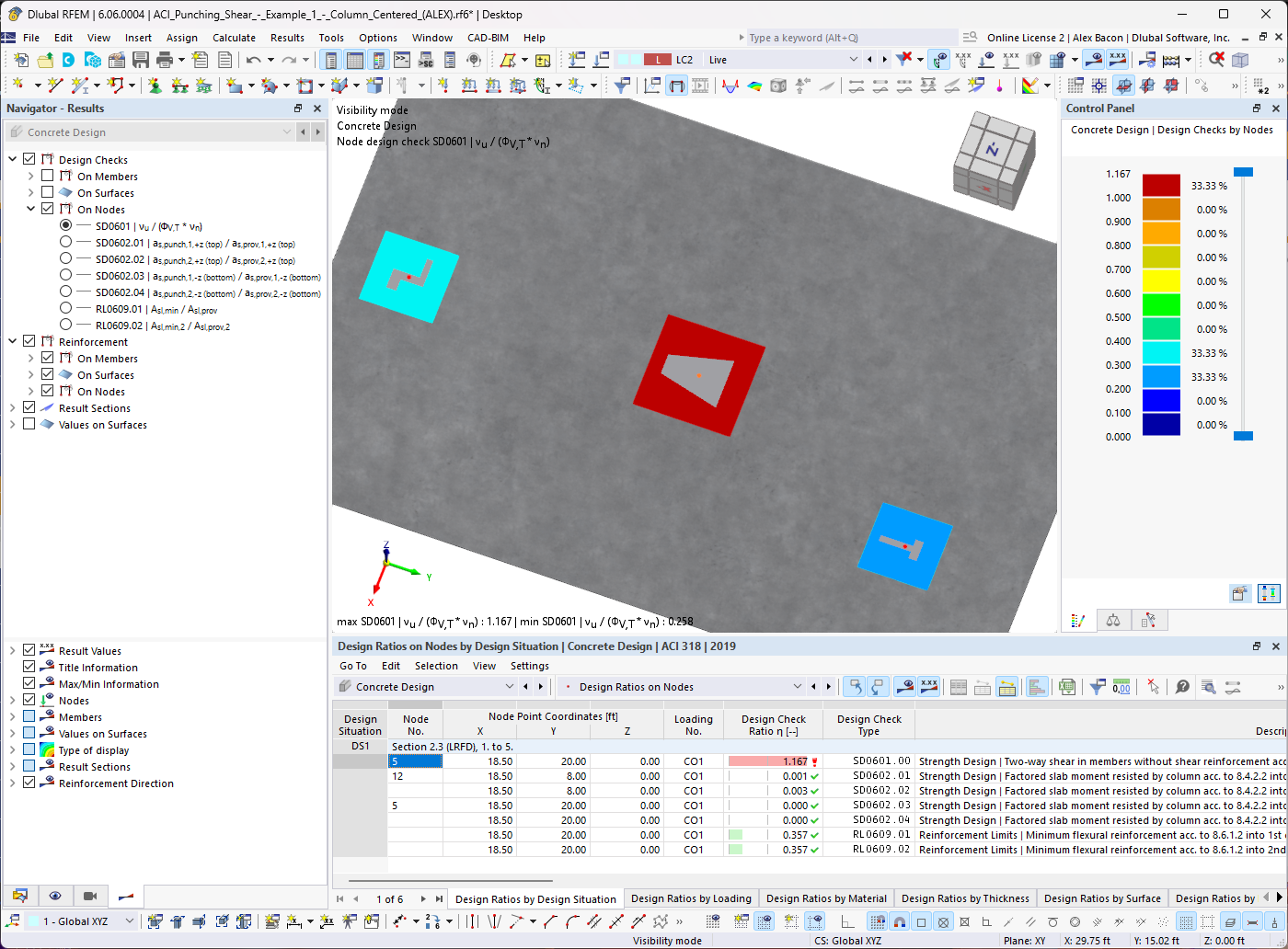
The seismic design result is categorized into two sections: member requirements and connection requirements.
The "Seismic Requirements" include the Required Flexural Strength and the Required Shear Strength of the beam-to-column connection for moment frames. They are listed in the ‘Moment Frame Connection by Member’ tab. For braced frames, the Required Connection Tensile Strength and the Required Connection Compressive Strength of the brace are listed in the ‘Brace Connection by Member’ tab.
The program provides the performed design checks in tables. The design check details clearly display the formulas and references to the standard.
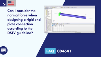
Can I consider the normal force when designing a rigid end plate connection according to the DSTV guideline?
In RF‑/JOINTS Steel - DSTV, I get the notes "Wrong geometry" and "Invalid material". Which entries do I have to adjust?
I designed a steel connection using RF‑JOINTS, then created a model to compare it in RFEM. Why are the results not identical?
Why do I obtain different results for the same end plate joint in RF‑/JOINTS Steel - DSTV and RF‑/JOINTS Steel - Rigid?
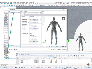
How do I define a plastic hinge in RFEM 6?
How can I exchange data between RFEM 6 / RSTAB 9 and IDEA StatiCa?


Recommended Products for You
RFEM 6 | Main Program RFEM 6

The new generation of 3D FEA software is used for the structural analysis of members, surfaces, and solids.
Price of First License
4,170.00 USD
RFEM 6 | Design

The Steel Design add-on performs the ultimate and serviceability limit state design checks of steel members according to various standards.
Price of First License
2,550.00 USD
RFEM 6 | Joints
.png?mw=600&hash=49b6a289915d28aa461360f7308b092631b1446e)
The Steel Joints add-on for RFEM allows you to analyze steel connections using an FE model. The FE model is generated automatically in the background and can be controlled via the simple and familiar input of components.
Price of First License
2,110.00 USD
RFEM 6 | Additional Analysis

The Torsional Warping (7 DOF) add-on allows you to consider cross-section warping as an additional degree of freedom when calculating members.
Price of First License
1,480.00 USD
RFEM 6 | Additional Analysis

The Nonlinear Material Behavior add-on allows you to consider material nonlinearities in RFEM for example, isotropic plastic, orthotropic plastic, isotropic damage).
Price of First License
1,480.00 USD
RFEM 6 | Additional Analysis

The Structure Stability add-on performs stability analysis of structures. It determines critical load factors and the corresponding stability modes.
Price of First License
1,300.00 USD
RFEM 6 | Additional Analysis

The Construction Stages Analysis (CSA) add-on allows for considering the construction process of structures (member, surface, and solid structures) in RFEM.
Price of First License
1,570.00 USD
RFEM 6 | Additional Analysis

The Time-Dependent Analysis (TDA) add-on allows you to consider the time-dependent material behavior of members. The long-term effects, such as creep, shrinkage, and aging, can influence the distribution of internal forces, depending on the structure.
Price of First License
1,030.00 USD
RFEM 6 | Additional Analysis

The Form-Finding add-on finds the optimal shape of members subjected to axial forces and tension-loaded surface models. The shape is determined by the equilibrium between the member axial force or the membrane stress and the existing boundary conditions.
Price of First License
2,060.00 USD
RFEM 6 | Dynamic Analysis

The Modal Analysis add-on allows for the calculation of eigenvalues, natural frequencies, and natural periods for member, surface, and solid models.
Price of First License
1,210.00 USD
RFEM 6 | Dynamic Analysis

Using the Pushover Analysis add-on, you can analyze the seismic actions on a particular building, and thus assess whether the building can withstand an earthquake.
Price of First License
1,300.00 USD
RFEM 6 | Special Solutions

The Building Model add-on for RFEM allows you to define and manipulate a building using stories. The stories can be adjusted in many ways afterwards. The information about stories and the entire model (center of gravity) is displayed in tables and graphics.
Price of First License
1,660.00 USD
RFEM 6 | Design

The Stress-Strain Analysis add-on performs general stress analysis by calculating the existing stresses and comparing them with the limit stresses.
Price of First License
1,210.00 USD
RSTAB 9 | Main Program RSTAB 9

The modern 3D structural analysis and design program is suitable for the structural and dynamic analysis of beam structures as well as the design of concrete, steel, timber, and other materials.
Price of First License
2,910.00 USD
RSTAB 9 | Design
The Steel Design add-on performs the ultimate and serviceability limit state design checks of steel members according to various standards.
Price of First License
2,550.00 USD
RSTAB 9 | Additional Analysis
The Structure Stability add-on performs the stability analysis of structures. It determines critical load factors and the corresponding stability modes.
Price of First License
1,300.00 USD
RSTAB 9 | Design
The Stress-Strain Analysis add-on performs a general stress analysis by calculating the existing stresses and comparing them to the limit stresses.
Price of First License
1,120.00 USD
RSTAB 9 | Additional Analysis
The Torsional Warping (7 DOF) add-on allows for considering cross-section warping as an additional degree of freedom when calculating members.
Price of First License
1,480.00 USD
RSTAB 9 | Dynamic Analysis
The Modal Analysis add-on allows for the calculation of eigenvalues, natural frequencies, and natural periods for member, surface, and solid models.
Price of First License
1,210.00 USD
RSTAB 9 | Dynamic Analysis
Earthquakes may have a significant impact on the deformation behavior of buildings. A pushover analysis allows you to analyze the deformation behavior of buildings and compare them with seismic actions. Using the Pushover Analysis add-on, you can analyze the seismic actions on a particular building, and thus assess whether the building can withstand the earthquake.
Price of First License
1,300.00 USD