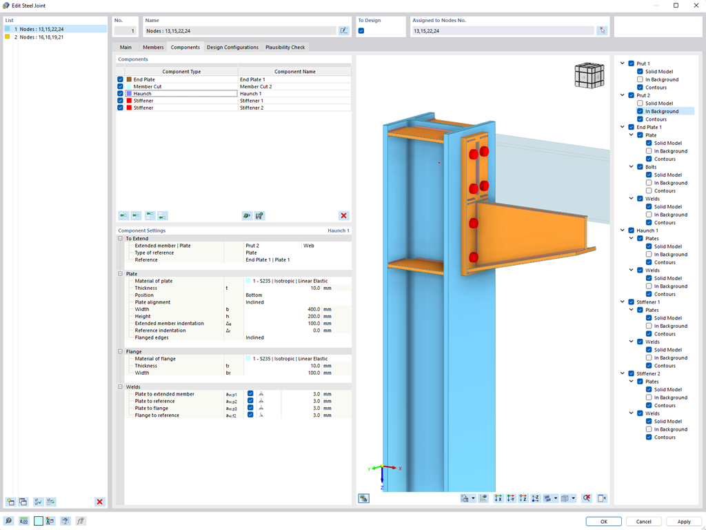
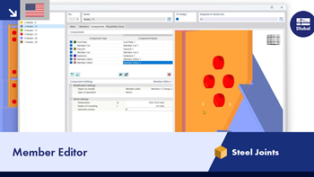
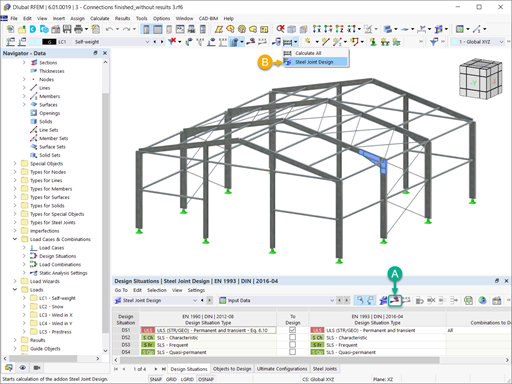
- Selection of nodes in the RFEM model, automatic recognition and assignment of the members connected to the node
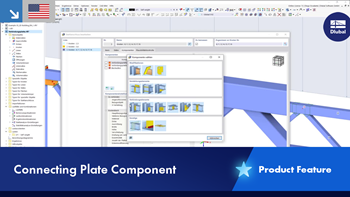
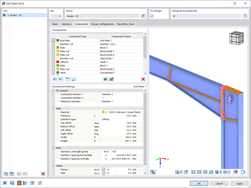
- Many predefined components available for easy input of typical connection situations (for example, end plates, cleats, fin plates)
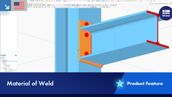
- Universally applicable basic components (plates, welds, auxiliary planes) for entering complex connection situations
- No manual editing of the FE model required by the user, the essential calculation settings can be changed via the configuration settings
- Automatic adaptation of the connection geometry, even if the members are subsequently edited, due to the relative relation of the components to each other
- Parallel to the input, a plausibility check is carried out by the program to quickly detect missing input or collisions, for example
- Graphical display of the connection geometry that is updated in parallel with the input
Steel Joints | Input
Do you have any questions?


Length: 00:50:32 min
Length: 00:58:09 min
Length: 00:48:24 min
Length: 00:01:52 min
Length: 00:00:35 min
Length: 00:00:19 min
Length: 00:49:16 min
Length: 00:01:20 min
Length: 00:45:06 min


The advantage of the RFEM 6 Steel Joints add-on is that you can analyze steel connections using an FE model for which the modeling runs fully automatically in the background. The input of the steel joint components that control the modeling can be done by defining the components manually, or by using the available templates in the library. The latter method is included in a previous Knowledge Base article titled “Defining Steel Joint Components Using the Library". The definition of parameters for the design of steel joints is the topic of the Knowledge Base article “Designing Steel Joints in RFEM 6".
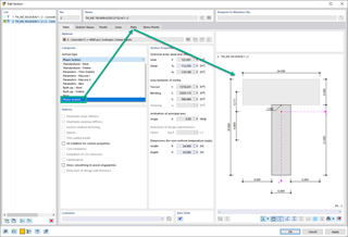
Steel connections in RFEM 6 are defined as an assembly of components. In the new Steel Joints add-on, universally applicable basic components (plates, welds, auxiliary planes) are available for entering complex connection situations. The methods with which connections can be defined are considered in two previous Knowledge Base articles: “A Novel Approach to Designing Steel Joints in RFEM 6" and “Defining Steel Joint Components Using the Library".

The three types of moment frames (Ordinary, Intermediate, Special) are available in the Steel Design add-on of RFEM 6. The seismic design result according to AISC 341-22 is categorized into two sections: member requirements and connection requirements.

The Steel Design add-on in RFEM 6 now offers the ability to perform seismic design according to AISC 341-16 and AISC 341-22. Five types of seismic force-resisting systems (SFRS) are currently available.


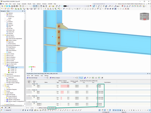
In the Steel Joints add-on, you can classify the joint stiffness.
In addition to the initial stiffness, the table also shows the limit values for hinged and rigid connections for the selected internal forces N, My, and/or Mz. The resulting classification is then displayed in tables as "hinged", "semi-rigid", or "rigid".
Go to Explanatory Video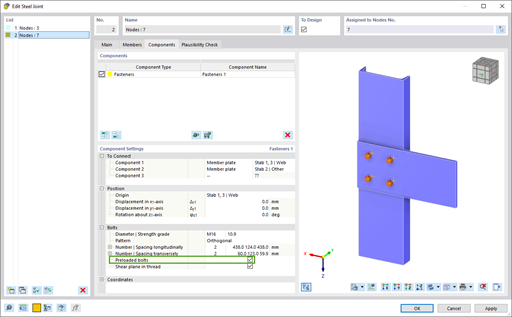
In the Steel Joints add-on, you have this option to consider the preloaded bolts in the calculation of all components.
You can easily activate the prestress using the check box in the bolt parameters, and it has an impact on the stress-strain analysis as well as the stiffness analysis.
Go to Explanatory Video
In the Steel Joint add-on, you can design the connections of members with composite cross-sections. Furthermore, you can perform joint design checks for almost all thin-walled cross-sections in the RFEM library.
Go to Explanatory Video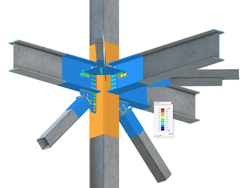
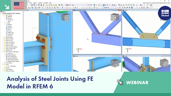
Complex Connection of Horizontal Beams to Column and Connection of Reinforcing Diagonals
The connection model was modeled using about 50 components. The model was created according to the real example of use in structure.
Which programs and add-ons are suitable for the structural analysis and design of steel structures?
How do I define a plastic hinge in RFEM 6?
How can I exchange data between RFEM 6 / RSTAB 9 and IDEA StatiCa?
How can I generate an area load on members via cells in RFEM 6 or RSTAB 9?
In the Steel Design add-on, I have set the boundary conditions in such a way that the I-beam flange is restrained against the horizontal displacement. I then calculated the critical load factors using the Structure Stability add-on, but with no effect on the critical load factor value. What is the reason for this?
Can I estimate which minimum cross-sections I should use before starting to design my model?


Recommended Products for You
RFEM 6 | Main Program RFEM 6

The new generation of 3D FEA software is used for the structural analysis of members, surfaces, and solids.
Price of First License
4,170.00 USD
RFEM 6 | Design

The Steel Design add-on performs the ultimate and serviceability limit state design checks of steel members according to various standards.
Price of First License
2,550.00 USD
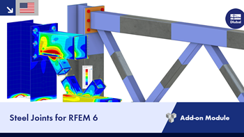
RFEM 6 | Joints
.png?mw=600&hash=49b6a289915d28aa461360f7308b092631b1446e)
The Steel Joints add-on for RFEM allows you to analyze steel connections using an FE model. The FE model is generated automatically in the background and can be controlled via the simple and familiar input of components.
Price of First License
2,110.00 USD
RFEM 6 | Additional Analysis

The Torsional Warping (7 DOF) add-on allows you to consider cross-section warping as an additional degree of freedom when calculating members.
Price of First License
1,480.00 USD
RFEM 6 | Additional Analysis

The Nonlinear Material Behavior add-on allows you to consider material nonlinearities in RFEM for example, isotropic plastic, orthotropic plastic, isotropic damage).
Price of First License
1,480.00 USD
RFEM 6 | Additional Analysis

The Structure Stability add-on performs stability analysis of structures. It determines critical load factors and the corresponding stability modes.
Price of First License
1,300.00 USD
RFEM 6 | Additional Analysis

The Construction Stages Analysis (CSA) add-on allows for considering the construction process of structures (member, surface, and solid structures) in RFEM.
Price of First License
1,570.00 USD
RFEM 6 | Additional Analysis

The Time-Dependent Analysis (TDA) add-on allows you to consider the time-dependent material behavior of members. The long-term effects, such as creep, shrinkage, and aging, can influence the distribution of internal forces, depending on the structure.
Price of First License
1,030.00 USD
RFEM 6 | Additional Analysis

The Form-Finding add-on finds the optimal shape of members subjected to axial forces and tension-loaded surface models. The shape is determined by the equilibrium between the member axial force or the membrane stress and the existing boundary conditions.
Price of First License
2,060.00 USD
RFEM 6 | Dynamic Analysis

The Modal Analysis add-on allows for the calculation of eigenvalues, natural frequencies, and natural periods for member, surface, and solid models.
Price of First License
1,210.00 USD
RFEM 6 | Dynamic Analysis

Using the Pushover Analysis add-on, you can analyze the seismic actions on a particular building, and thus assess whether the building can withstand an earthquake.
Price of First License
1,300.00 USD
RFEM 6 | Special Solutions

The Building Model add-on for RFEM allows you to define and manipulate a building using stories. The stories can be adjusted in many ways afterwards. The information about stories and the entire model (center of gravity) is displayed in tables and graphics.
Price of First License
1,660.00 USD
RFEM 6 | Design

The Stress-Strain Analysis add-on performs general stress analysis by calculating the existing stresses and comparing them with the limit stresses.
Price of First License
1,210.00 USD
RSTAB 9 | Main Program RSTAB 9

The modern 3D structural analysis and design program is suitable for the structural and dynamic analysis of beam structures as well as the design of concrete, steel, timber, and other materials.
Price of First License
2,910.00 USD
RSTAB 9 | Design
The Steel Design add-on performs the ultimate and serviceability limit state design checks of steel members according to various standards.
Price of First License
2,550.00 USD
RSTAB 9 | Additional Analysis
The Structure Stability add-on performs the stability analysis of structures. It determines critical load factors and the corresponding stability modes.
Price of First License
1,300.00 USD
RSTAB 9 | Design
The Stress-Strain Analysis add-on performs a general stress analysis by calculating the existing stresses and comparing them to the limit stresses.
Price of First License
1,120.00 USD
RSTAB 9 | Additional Analysis
The Torsional Warping (7 DOF) add-on allows for considering cross-section warping as an additional degree of freedom when calculating members.
Price of First License
1,480.00 USD
RSTAB 9 | Dynamic Analysis
The Modal Analysis add-on allows for the calculation of eigenvalues, natural frequencies, and natural periods for member, surface, and solid models.
Price of First License
1,210.00 USD
RSTAB 9 | Dynamic Analysis
Earthquakes may have a significant impact on the deformation behavior of buildings. A pushover analysis allows you to analyze the deformation behavior of buildings and compare them with seismic actions. Using the Pushover Analysis add-on, you can analyze the seismic actions on a particular building, and thus assess whether the building can withstand the earthquake.
Price of First License
1,300.00 USD