| Structural Engineering | CBF Engineering GmbH Development Engineering Rollbergstraße 70 12053 Berlin, Germany Tel.: +49 (0) 30 / 62 78 63 12 |
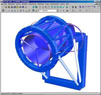
Load-Bearing Appliance for Crane-Free Assembly


Length: 00:01:27 min
Length: 00:00:31 min

Length: 00:00:54 min
Length: 00:00:22 min
Length: 00:01:33 min
Length: 00:03:54 min
Length: 00:00:29 min
Length: 00:00:00 min


Dlubal_KohlA_Rev1.png?mw=350&hash=f8d2ccd6ebb5a4c58d1c98f433e9f5171a41f581)


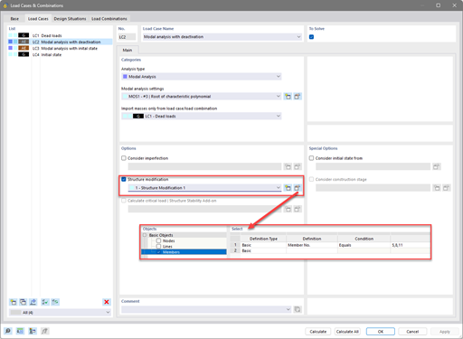
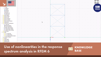
Both the determination of natural vibrations and the response spectrum analysis are always performed on a linear system. If nonlinearities exist in the system, they are linearized and thus not taken into account. They are caused by, for example, tension members, nonlinear supports, or nonlinear hinges. This article shows how you can handle them in a dynamic analysis.

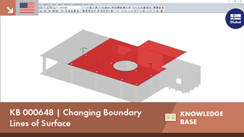
If the geometry of a surface for which you must remove some of the existing boundary lines changes subsequently, you do not need to redefine the surface.
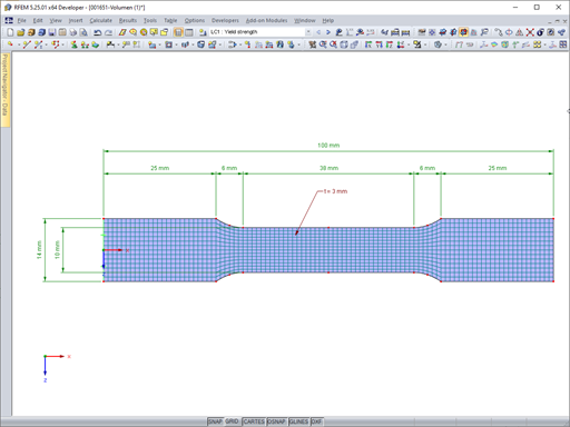
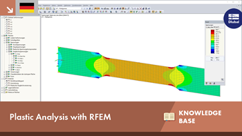
The elastic deformations of a structural component due to a load are based on Hooke's law, which describes a linear stress-strain relation. They are reversible: After the relief, the component returns to its original shape. However, plastic deformations lead to irreversible deformations. The plastic strains are usually considerably larger than the elastic deformations. For plastic stresses of ductile materials such as steel, yielding effects occur where the increase in deformation is accompanied by hardening. They lead to permanent deformations - and in extreme cases to the destruction of the structural component.
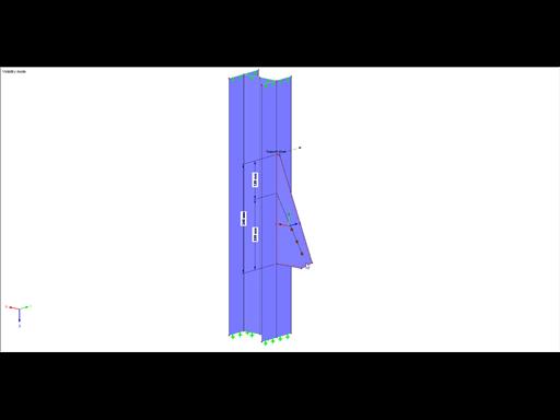
The European standard EN 1993-1-8, Section 4.5.3.3. provides the user with a simplified method for the ultimate limit state design of fillet welds. According to the standard, the design is fulfilled if the design value of the resultant acting on the fillet weld area is smaller than the design value of the weld's load-bearing capacity. Thus, if you want to dimension the weld for a surface model, you will be faced with a variety of results due to the nature of FEM calculations. Therefore, we show in the following text how to determine the force components from the model.


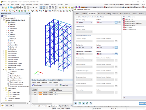
The design of cold-formed steel members according to the AISI S100-16 / CSA S136-16 is available in RFEM 6. Design can be accessed by selecting “AISC 360” or “CSA S16” as the standard in the Steel Design Add-on. “AISI S100” or “CSA S136” is then automatically selected for the cold-formed design.
RFEM applies the Direct Strength Method (DSM) to calculate the elastic buckling load of the member. The Direct Strength Method offers two types of solutions, numerical (Finite Strip Method) and analytical (Specification). The FSM signature curve and buckling shapes can be viewed under Sections.
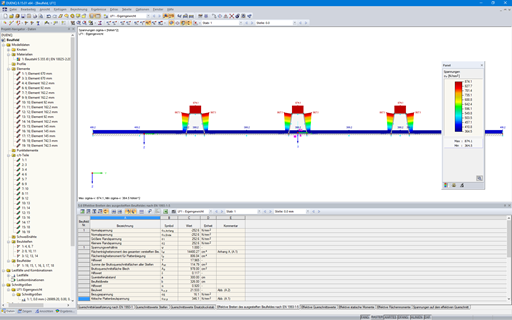
In SHAPE-THIN 8, the effective cross-section of stiffened buckling panels can be calculated according to EN 1993-1-5, Cl. 4.5.
The critical buckling stress is calculated according to EN 1993-1-5, Annex A.1 for buckling panels with at least 3 longitudinal stiffeners, or according to EN 1993-1-5, Annex A.2 for buckling panels with one or two stiffeners in the compression zone. The design for torsional buckling safety is also performed.

In the "Edit Section" dialog box, you can display the buckling shapes of the Finite Strip Method (FSM) as a 3D graphic.

- Design of five types of seismic force-resisting systems (SFRS) includes Special Moment Frame (SMF), Intermediate Moment Frame (IMF), Ordinary Moment Frame (OMF), Ordinary Concentrically Braced Frame (OCBF), and Special Concentrically Braced Frame (SCBF)
- Ductility check of the width-to thickness ratios for webs and flanges
- Calculation of the required strength and stiffness for stability bracing of beams
- Calculation of the maximum spacing for stability bracing of beams
- Calculation of the required strength at hinge locations for stability bracing of beams
- Calculation of the column required strength with the option to neglect all bending moments, shear, and torsion for overstrength limit state
- Design check of column and brace slenderness ratios
I want to create a mapped mesh for a circular hole plate. Is it possible to generate such a mesh in RFEM?
Is it possible to set user-defined values when viewing solid stress results?
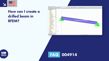
How can I create a drilled beam in RFEM?
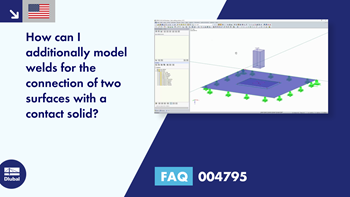
How can I additionally model welds for the connection of two surfaces with a contact solid?
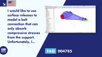
I would like to use surface releases to model a bolt connection that can only absorb compressive stresses from the support. Unfortunately, I cannot do this because my model is always unstable. Is there a template model?
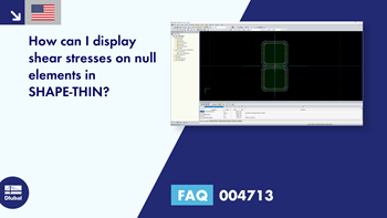
How can I display shear stresses on null elements in SHAPE‑THIN?


Recommended Products for You
RFEM 6 | Main Program RFEM 6

The new generation of 3D FEA software is used for the structural analysis of members, surfaces, and solids.
Price of First License
4,170.00 USD
RFEM 6 | Design

The Steel Design add-on performs the ultimate and serviceability limit state design checks of steel members according to various standards.
Price of First License
2,550.00 USD
RFEM 6 | Joints
.png?mw=600&hash=49b6a289915d28aa461360f7308b092631b1446e)
The Steel Joints add-on for RFEM allows you to analyze steel connections using an FE model. The FE model is generated automatically in the background and can be controlled via the simple and familiar input of components.
Price of First License
2,110.00 USD
RFEM 6 | Additional Analysis

The Torsional Warping (7 DOF) add-on allows you to consider cross-section warping as an additional degree of freedom when calculating members.
Price of First License
1,480.00 USD
RFEM 6 | Additional Analysis

The Nonlinear Material Behavior add-on allows you to consider material nonlinearities in RFEM for example, isotropic plastic, orthotropic plastic, isotropic damage).
Price of First License
1,480.00 USD
RFEM 6 | Additional Analysis

The Structure Stability add-on performs stability analysis of structures. It determines critical load factors and the corresponding stability modes.
Price of First License
1,300.00 USD
RFEM 6 | Additional Analysis

The Construction Stages Analysis (CSA) add-on allows for considering the construction process of structures (member, surface, and solid structures) in RFEM.
Price of First License
1,570.00 USD
RFEM 6 | Additional Analysis

The Time-Dependent Analysis (TDA) add-on allows you to consider the time-dependent material behavior of members. The long-term effects, such as creep, shrinkage, and aging, can influence the distribution of internal forces, depending on the structure.
Price of First License
1,030.00 USD
RFEM 6 | Additional Analysis

The Form-Finding add-on finds the optimal shape of members subjected to axial forces and tension-loaded surface models. The shape is determined by the equilibrium between the member axial force or the membrane stress and the existing boundary conditions.
Price of First License
2,060.00 USD
RFEM 6 | Dynamic Analysis

The Modal Analysis add-on allows for the calculation of eigenvalues, natural frequencies, and natural periods for member, surface, and solid models.
Price of First License
1,210.00 USD
RFEM 6 | Dynamic Analysis

Using the Pushover Analysis add-on, you can analyze the seismic actions on a particular building, and thus assess whether the building can withstand an earthquake.
Price of First License
1,300.00 USD
RFEM 6 | Special Solutions

The Building Model add-on for RFEM allows you to define and manipulate a building using stories. The stories can be adjusted in many ways afterwards. The information about stories and the entire model (center of gravity) is displayed in tables and graphics.
Price of First License
1,660.00 USD
RFEM 6 | Design

The Stress-Strain Analysis add-on performs general stress analysis by calculating the existing stresses and comparing them with the limit stresses.
Price of First License
1,210.00 USD
RSTAB 9 | Main Program RSTAB 9

The modern 3D structural analysis and design program is suitable for the structural and dynamic analysis of beam structures as well as the design of concrete, steel, timber, and other materials.
Price of First License
2,910.00 USD
RSTAB 9 | Design
The Steel Design add-on performs the ultimate and serviceability limit state design checks of steel members according to various standards.
Price of First License
2,550.00 USD
RSTAB 9 | Additional Analysis
The Structure Stability add-on performs the stability analysis of structures. It determines critical load factors and the corresponding stability modes.
Price of First License
1,300.00 USD
RSTAB 9 | Design
The Stress-Strain Analysis add-on performs a general stress analysis by calculating the existing stresses and comparing them to the limit stresses.
Price of First License
1,120.00 USD
RSTAB 9 | Additional Analysis
The Torsional Warping (7 DOF) add-on allows for considering cross-section warping as an additional degree of freedom when calculating members.
Price of First License
1,480.00 USD
RSTAB 9 | Dynamic Analysis
The Modal Analysis add-on allows for the calculation of eigenvalues, natural frequencies, and natural periods for member, surface, and solid models.
Price of First License
1,210.00 USD
RSTAB 9 | Dynamic Analysis
Earthquakes may have a significant impact on the deformation behavior of buildings. A pushover analysis allows you to analyze the deformation behavior of buildings and compare them with seismic actions. Using the Pushover Analysis add-on, you can analyze the seismic actions on a particular building, and thus assess whether the building can withstand the earthquake.
Price of First License
1,300.00 USD