


2024-05-30
009221
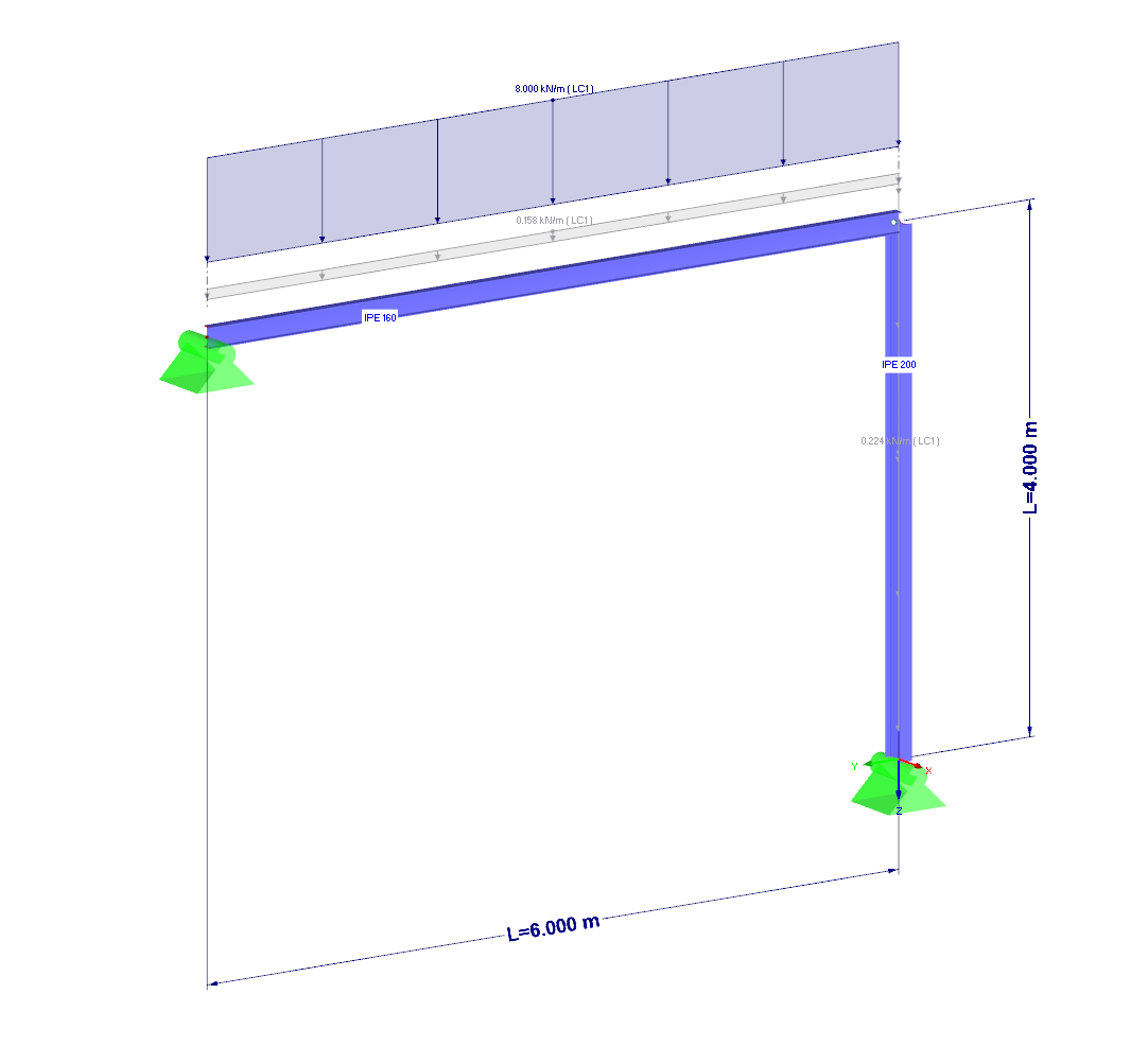
Structural System and Loading
2024-05-30
009222
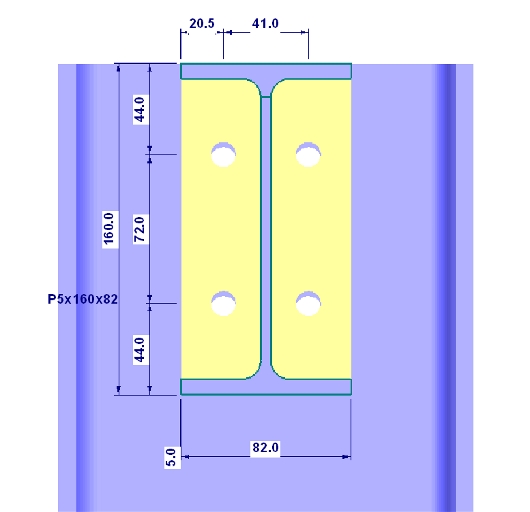
End Plate
2024-05-30
009223
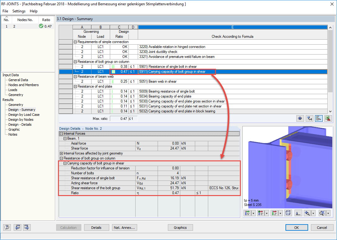
Summary of Design Checks in RF-JOINTS Steel - Pinned
2024-05-30
009224
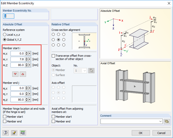
Definition of Member Eccentricity on Beam
2024-05-30
009225
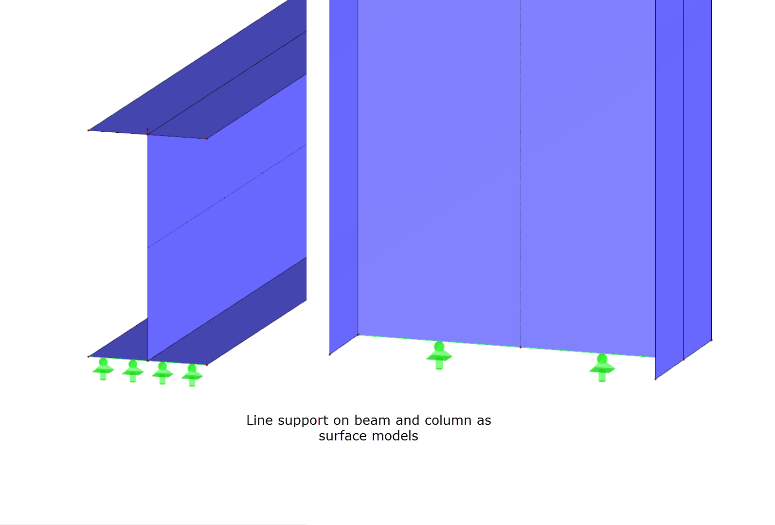
Line Support on Beam and Column
3D Model
Specifications
| Number of Nodes | 2 |
| Number of Lines | 1 |
| Number of Members | 1 |
| Number of Surfaces | 0 |
| Number of Solids | 0 |
| Number of Load Cases | 1 |
| Number of Load Combinations | 4 |
| Number of Result Combinations | 0 |
| Total Weight | 0,349 t |
| Dimensions (Metric) | 0,000 x 4,500 x 0,000 m |
| Dimensions (Imperial) | 0 x 14.76 x 0 feet |
2024-05-30
009226
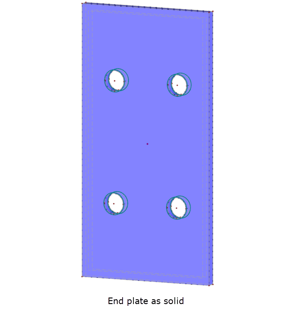
End Plate as Solid
2024-05-30
009227
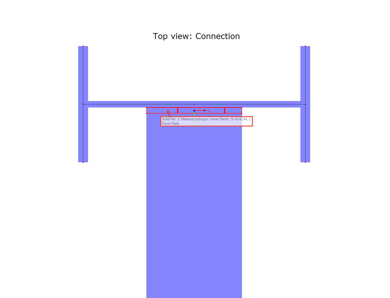
Top View of Connection in Z-Direction
3D Model
Specifications
| Number of Nodes | 2 |
| Number of Lines | 1 |
| Number of Members | 1 |
| Number of Surfaces | 0 |
| Number of Solids | 0 |
| Number of Load Cases | 1 |
| Number of Load Combinations | 4 |
| Number of Result Combinations | 0 |
| Total Weight | 0,349 t |
| Dimensions (Metric) | 0,000 x 4,500 x 0,000 m |
| Dimensions (Imperial) | 0 x 14.76 x 0 feet |
2024-05-30
009228
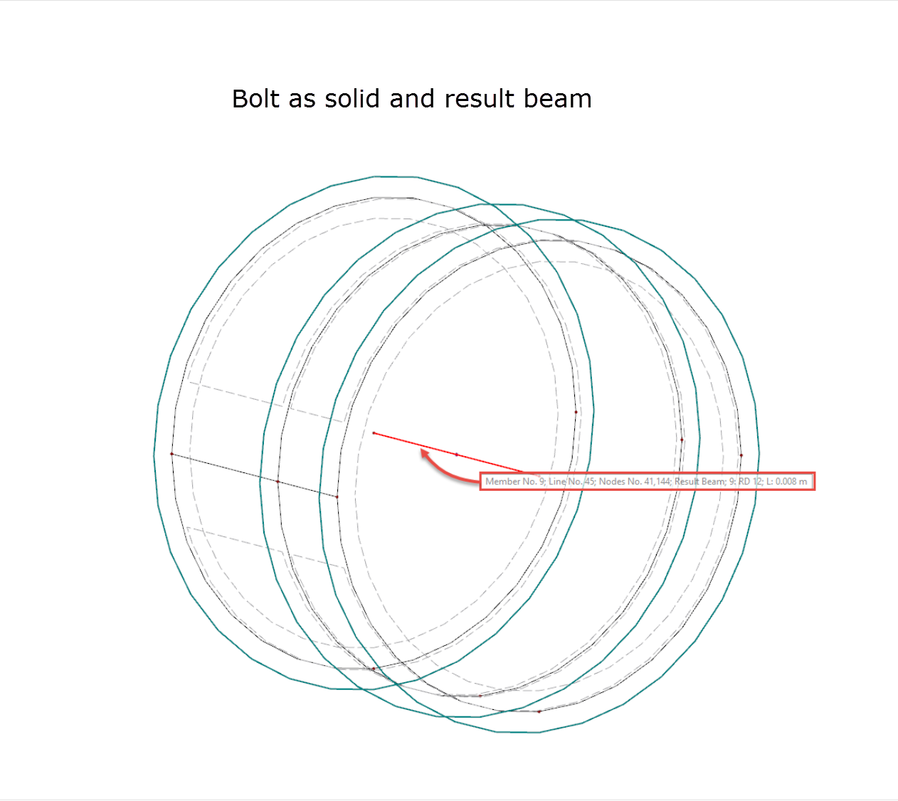
Bolt as Solid and Result Beam
2024-05-30
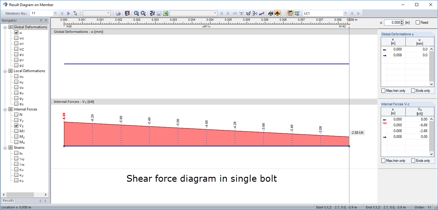
009229
Result Diagram of Shear Force of Bolt
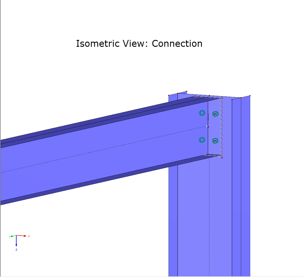
Isometry of Connection