


2024-05-30
026103
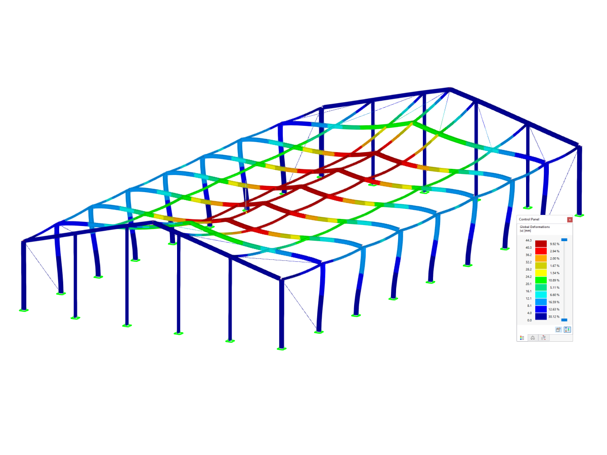
Steel Hall Under Load Deformation
Deformation analysis of a steel hall under load. Display of serviceability and results of the steel design.
The image shows the deformation of a steel hall under the influence of loads. It illustrates the serviceability and the results of a steel design. The visual model shows how the structure behaves under different loads and provides valuable insights for engineers. This analysis is crucial to ensure the safety and stability of steel structures.
3D Model
Specifications
| Number of Nodes | 89 |
| Number of Lines | 168 |
| Number of Members | 168 |
| Number of Load Cases | 1 |
| Total Weight | 53.542 t |
| Dimensions (Metric) | 26.077 x 51.077 x 9.888 m |
| Dimensions (Imperial) | 85.55 x 167.58 x 32.44 feet |
| Program Version | 5.23.02 |
2024-05-30
010197
Visual Aids for Defining Support Conditions for Member Sets in Design According to EN 1993-1-1, Section 6.3.4
Definition of support conditions in member sets according to EN 1993-1-1
The image shows visual aids for defining support conditions when performing design checks on member sets according to EN 1993-1-1, Section 6.3.4. This includes aspects of stability analysis and torsional stiffness when designing steel structures.
3D Model
Specifications
| Number of Nodes | 89 |
| Number of Lines | 168 |
| Number of Members | 168 |
| Number of Load Cases | 1 |
| Total Weight | 53.542 t |
| Dimensions (Metric) | 26.077 x 51.077 x 9.888 m |
| Dimensions (Imperial) | 85.55 x 167.58 x 32.44 feet |
| Program Version | 5.23.02 |
2024-05-30
020903
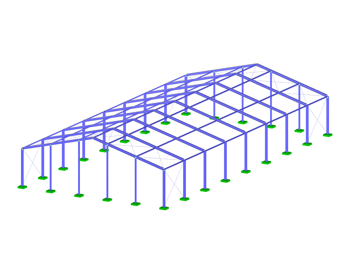
Steel Hall
Steel structure of Simple Hall
The image shows a steel hall. The arrangement of the secondary beams and the geometry of the roof are clearly visible. The transparent display makes the structural composition visible.
3D Model
Specifications
| Number of Nodes | 89 |
| Number of Lines | 168 |
| Number of Members | 168 |
| Number of Load Cases | 1 |
| Total Weight | 53.542 t |
| Dimensions (Metric) | 26.077 x 51.077 x 9.888 m |
| Dimensions (Imperial) | 85.55 x 167.58 x 32.44 feet |
| Program Version | 5.23.02 |