


2024-05-30
026982
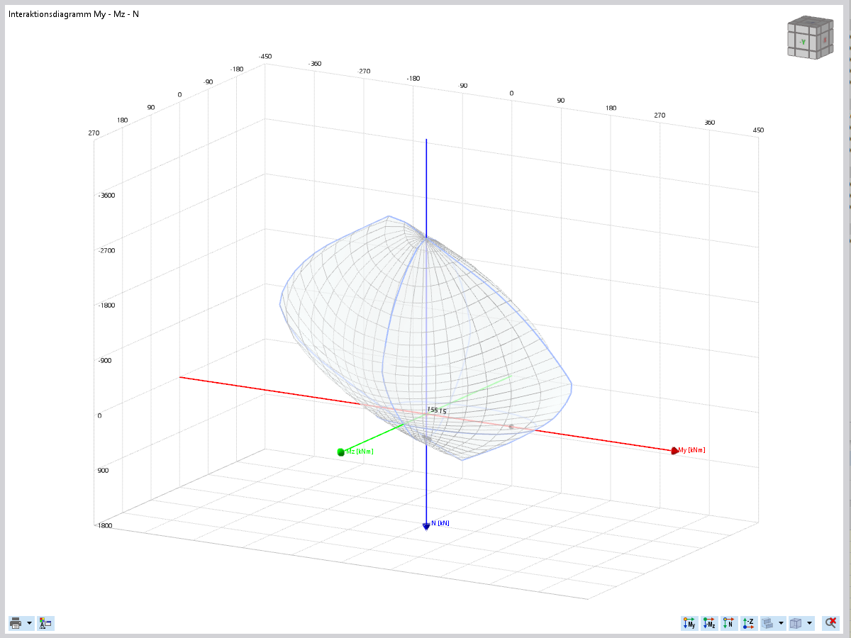
3D Interaction Diagram with Reverse Labeling
3D interaction diagram for the load-bearing capacity of reinforced concrete cross-sections with moments and axial force.
The image shows a three-dimensional My-Mz-N interaction diagram for the display of the ultimate limit state of reinforced concrete cross-sections. This analysis allows for a visual evaluation of the ultimate limit state under consideration of moments and axial force. The diagram illustrates the load-bearing capacity and provides notes on any exceedance of the material limits. Users can customize the appearance of the diagram functions to meet specific requirements.
2025-03-24
026983
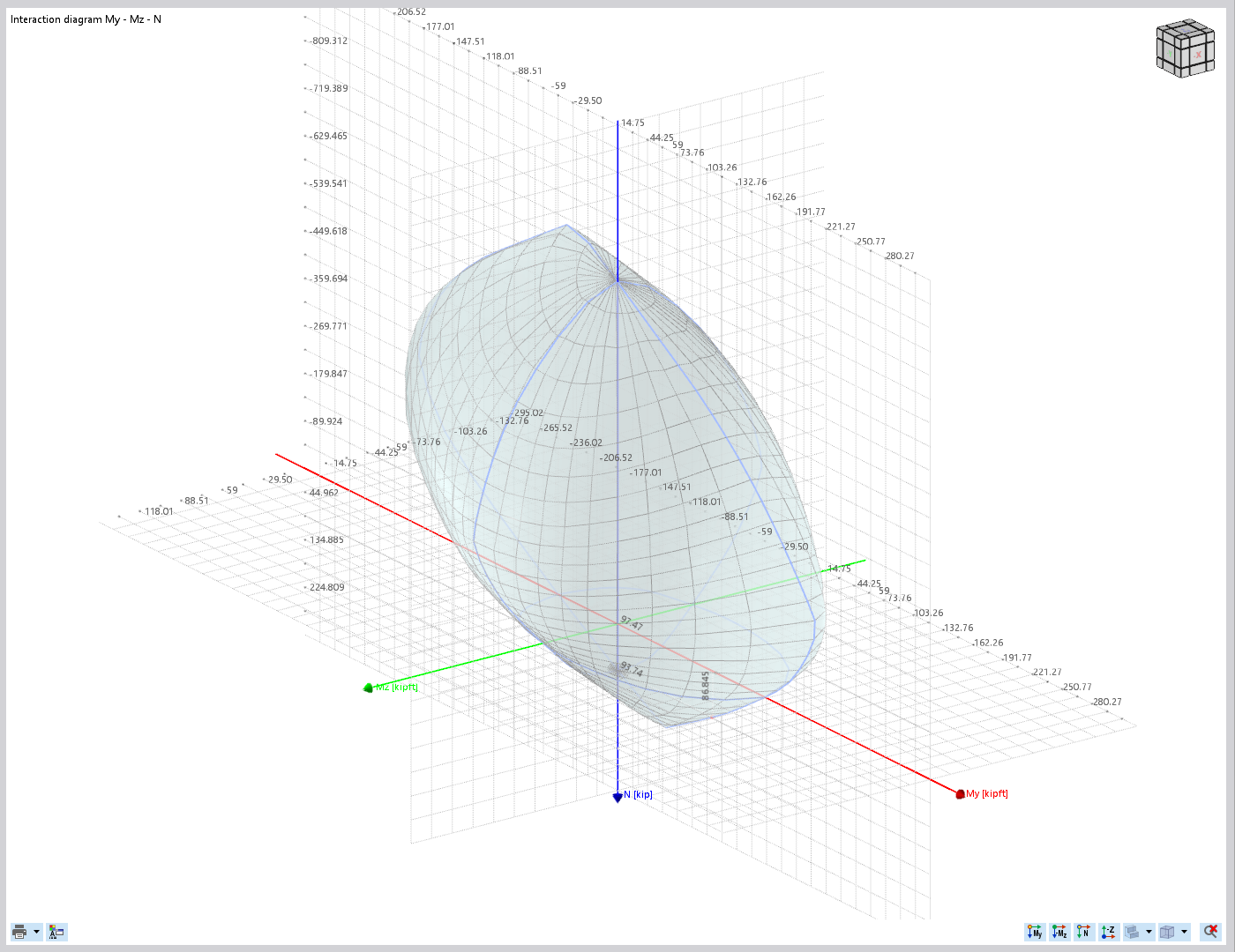
3D Interaction Diagram with Axial Labeling
3D interaction diagram shows axial labels for structural load analysis.
The image shows a 3D interaction diagram used to visualize and analyze loads in a structural application. The axes are clearly labeled and provide insights into the distribution of the loads.
2025-03-24
026984
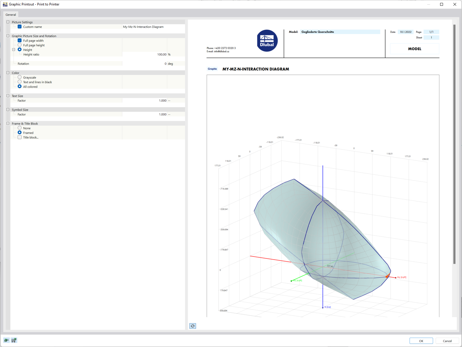
Printout of My-Mz-N Interaction Diagram
My-Mz-N interaction diagram for the display of moment-force relation in a structural analysis system.
The My-Mz-N interaction diagram shows the relationship between moments and axial forces in a structural analysis system. It is used to illustrate the capacity of a structural component under various load combinations. Engineers can use the diagram to efficiently evaluate whether specific loads exceed the capacity. Such diagrams are essential for safe structural design.
2025-03-24
026985
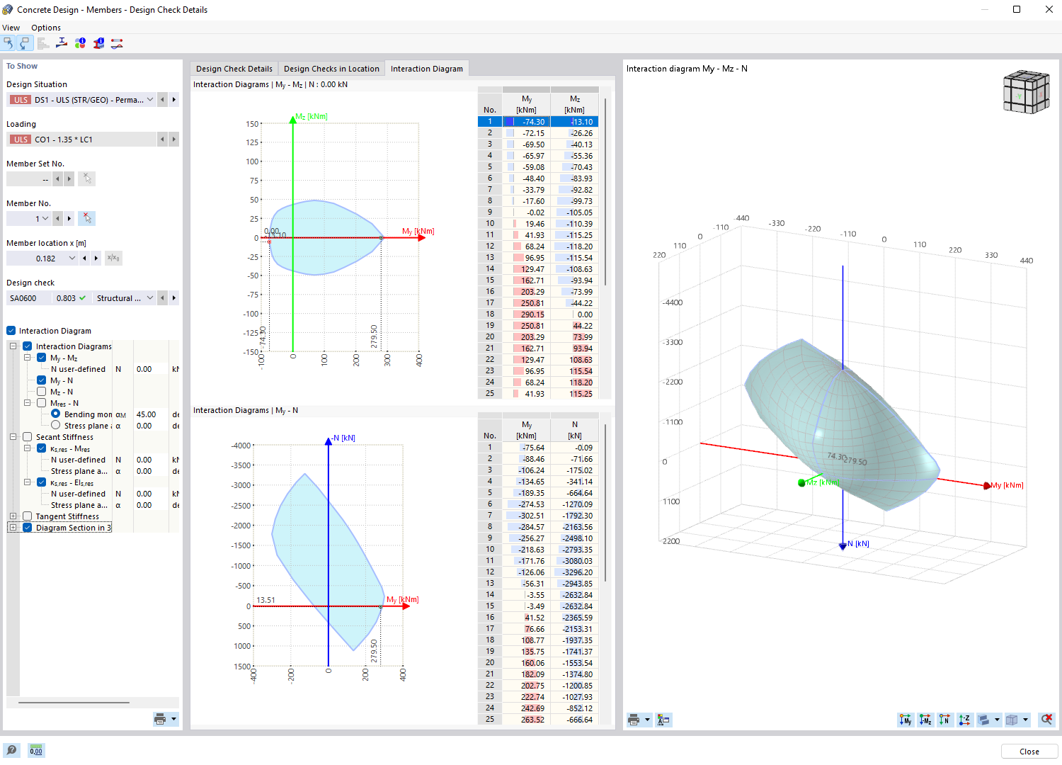
Result Output Using Interaction Diagrams
Interaction diagram for analyzing structural behavior, suitable for design and optimization of materials.
The image shows the results output of an interaction diagram used to evaluate the structural behavior of a building material element. The diagrams help engineers to precisely analyze material limits and capacities. This type of diagram is essential for design checks and optimization of structures, as it displays the interactions between different forces and moments, allowing for informed decisions. Image source not specified.