


2024-05-30
026990
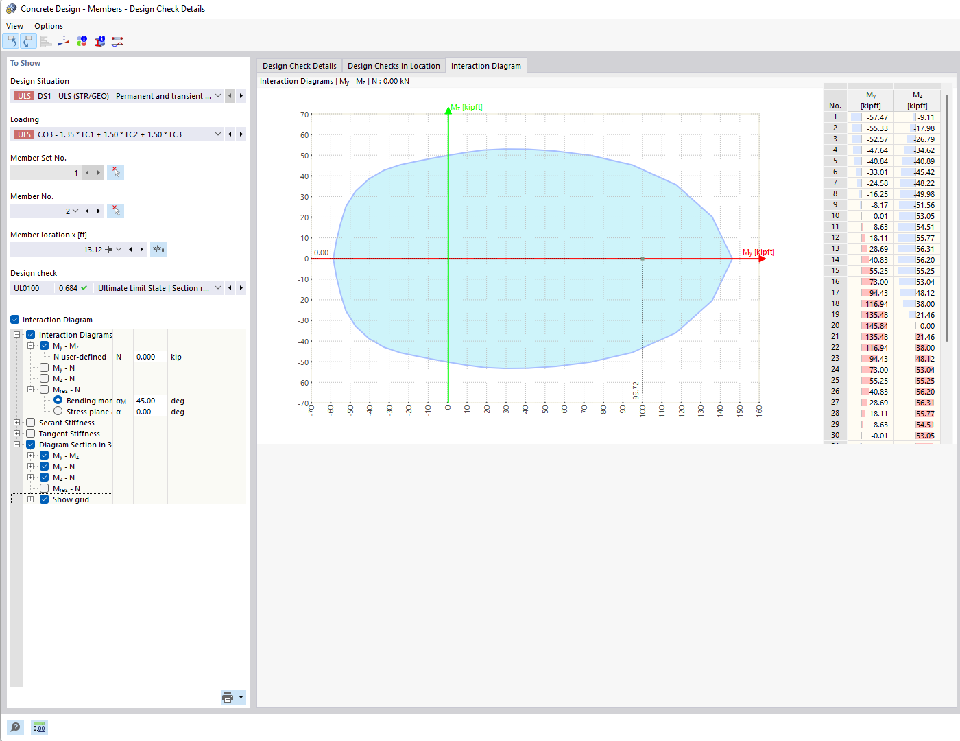
Moment-Moment Interaction Diagram
Visualization of the biaxial bending resistance of a reinforced concrete cross-section using a moment-moment interaction diagram.
The image shows a moment-moment interaction diagram for reinforced concrete cross-sections. This technical diagram is used to determine the biaxial bending resistance of a reinforced concrete cross-section. The My-Mz diagram displays a horizontal section of the three-dimensional diagram for a given axial force. It visualizes the relationship between the moments along two axes under the given axial force.
2025-03-24
026991
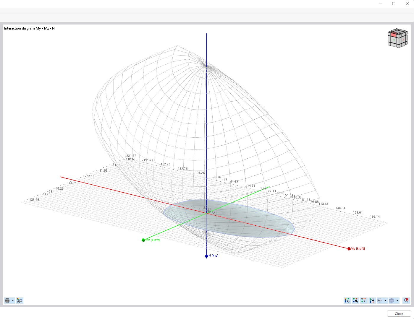
Section Plane for My-Mz Diagram in Transparent My-Mz-N Interaction Diagram
Moment-moment interaction diagram to determine the biaxial bending resistance of a reinforced concrete cross-section.
The image shows a My-Mz diagram that illustrates the biaxial bending resistance of a reinforced concrete cross-section. The diagram consists of a horizontal section through a complex three-dimensional interaction diagram at a certain axial force. This is used to analyze the moment distribution in the Y and Z axes. This graphical display supports the design checks of concrete structures with regard to their bending resistance.
2025-03-24
026993
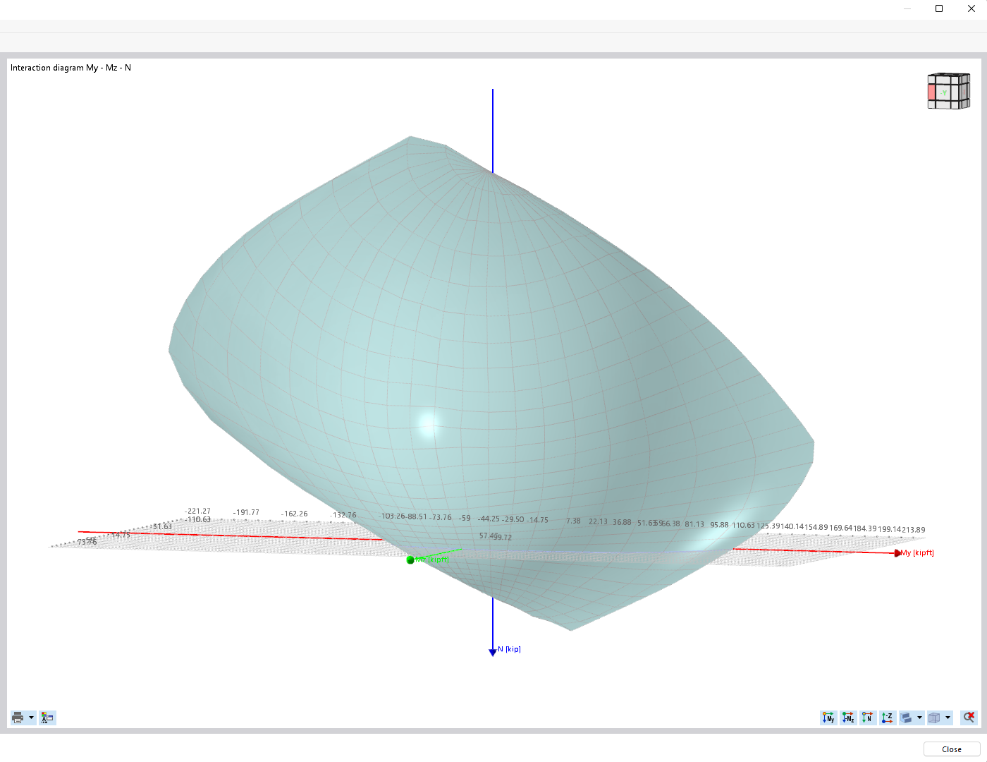
Section Plane for My-Mz Diagram in Filled My-Mz-N Interaction Diagram
Sectional plane shows the My-Mz diagram in the filled interaction diagram for the design checks of reinforced concrete cross-sections.
The image shows a three-dimensional My-Mz-N interaction diagram, which represents a horizontal section through the diagram for a given axial force N. The biaxial bending resistance of a reinforced concrete cross-section is emphasized by the section diagram. The diagram illustrates how My and Mz moments influence and illustrate the supporting capacity under consideration of different forces.