.png)
.png?mw=180&hash=a71bcc82eb37f1d4a6acc6ff7ac92a0d5c43b5f4)


2021-12-17
026995
Moment-Curvature Line
Display of an interaction diagram showing the biaxial bending resistance of a reinforced concrete cross-section.
The image shows a moment-moment interaction diagram for analyzing the biaxial bending resistance of a reinforced concrete cross-section. The diagram can be used to visualize the load-bearing capacity taking into account the axial force N. This diagram is part of a complex analysis that can be carried out in structural engineering software. The My-Mz diagram is a section type used in concrete design.
2025-03-24
027016
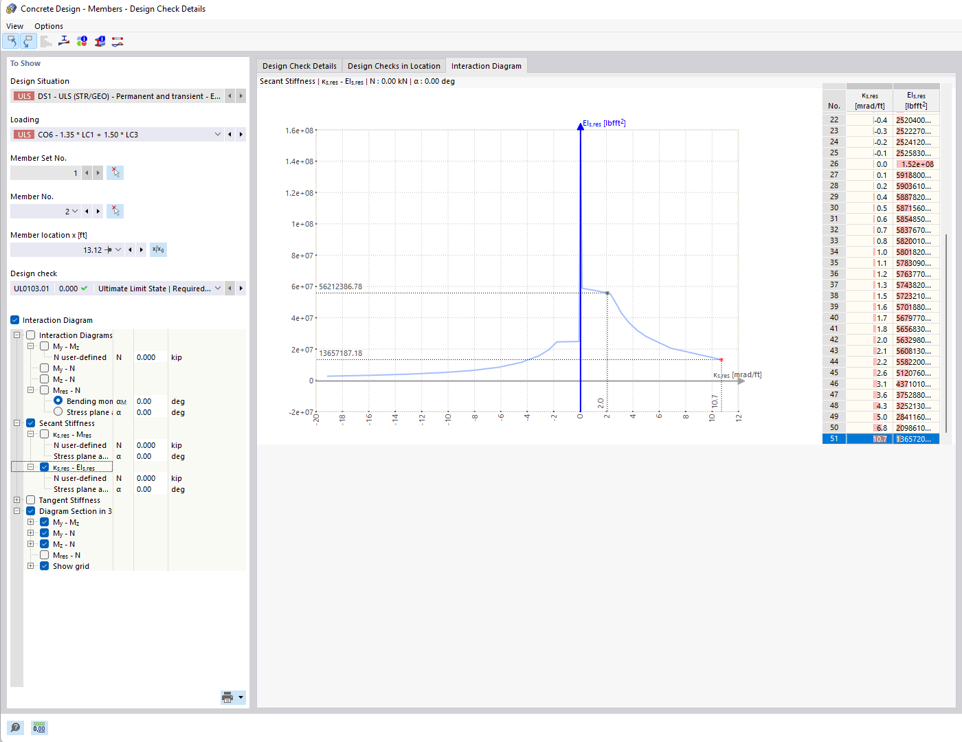
Secant Stiffness
Interaction diagram to determine the biaxial bending resistance of a reinforced concrete cross-section. It shows the My-Mz diagram for a given axial force N.
The image shows a moment-moment interaction diagram that analyzes the biaxial bending resistance of reinforced concrete cross-sections. A horizontal My-Mz diagram is used to visualize the interaction between moments and a given axial force N. The option of connecting to a three-dimensional interaction diagram allows the visualization of the section plane in space.
2025-03-24
027017
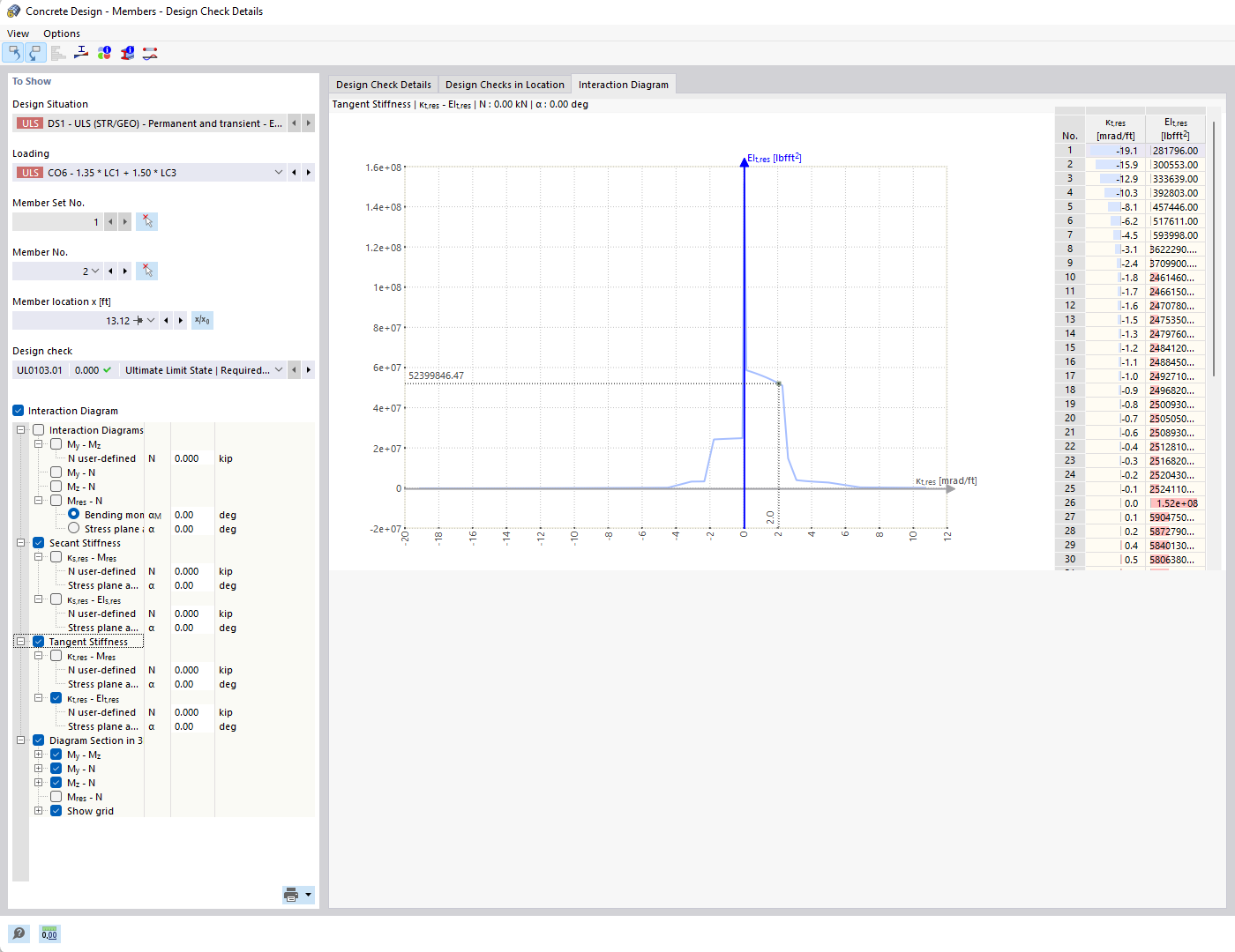
Tangential Stiffness
Interaction diagram illustrates bending resistance under biaxial loading. Optimization of concrete design based on sectioning.
The moment-moment interaction diagram shows the biaxial bending resistance of a reinforced concrete cross-section. It represents a horizontal section display within a 3D diagram and takes a given axial force into account. The combination of bending moments about two axes (My, Mz) is analyzed in the context of different load conditions. The diagram helps to optimize the concrete design by visualizing the resulting force balance.