2024-08-23
044001
RFEM 6
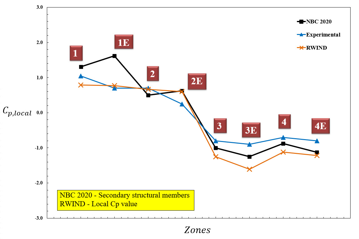
Figure 6: Diagram of Local Wind Pressure Value for Design of Secondary Structural Members
Used in
Validation Example for CC
p,ave
Value of Main and Secondary Structural Members for Low-Rise Building with 45-Degree Sloped Roof Comparison to NBC 2020 and Japanese Wind Tunnel Data Base
Share
Copy