
2024-12-03
054345
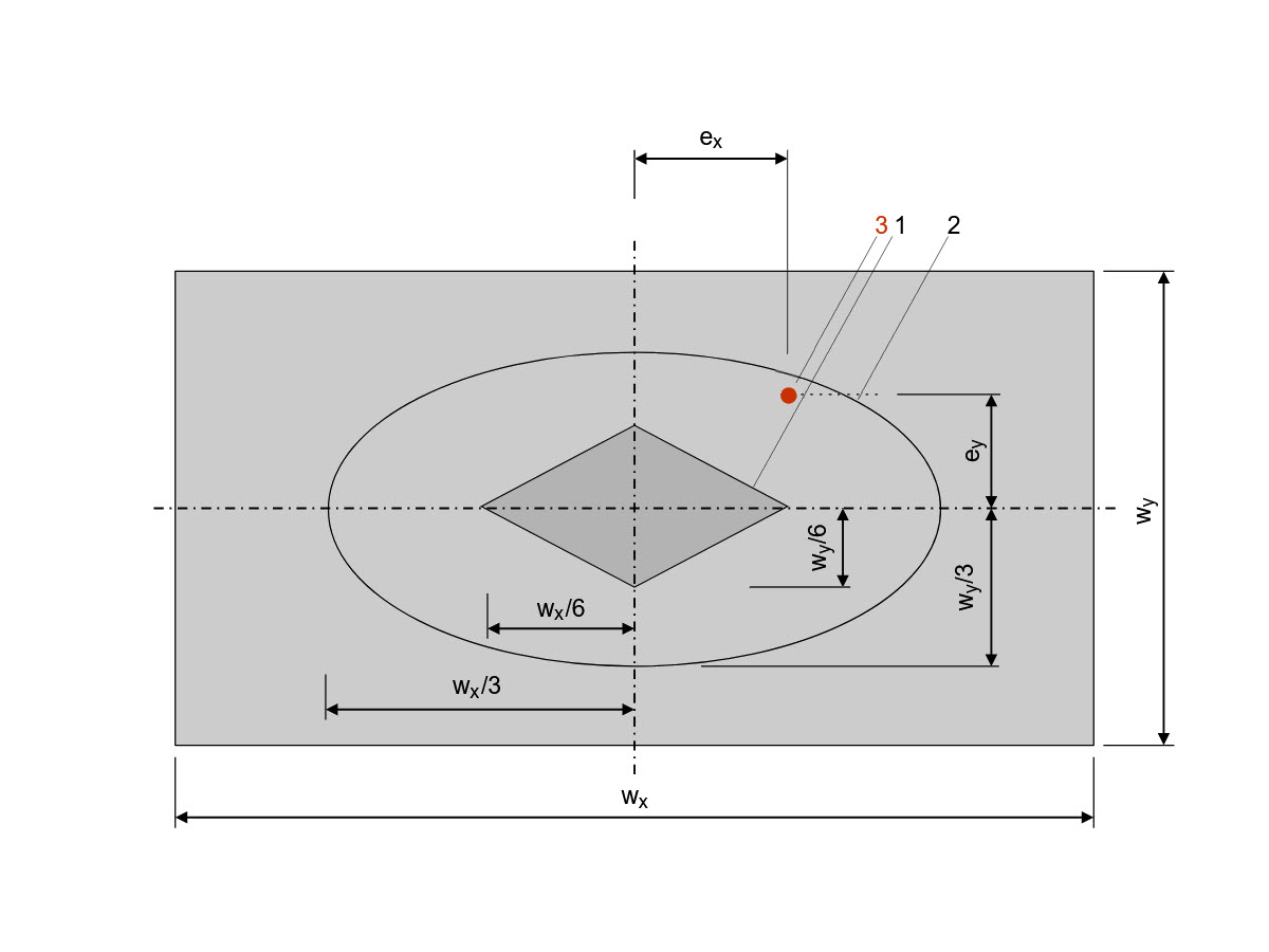
Illustration of 1st and 2nd Core Widths
A technical illustration to explain the maximum allowable eccentricities for maintaining the core widths for geotechnical design.
Illustration of 1st and 2nd Core Widths
Marking 1: The boundary of the 1st core width is represented by a rhombus.
Marking 2: The boundary of the 2nd core width is represented by an ellipse.
Marking 3: The point of application of the resultant is the point at which the entire resulting load acts on the foundation base.