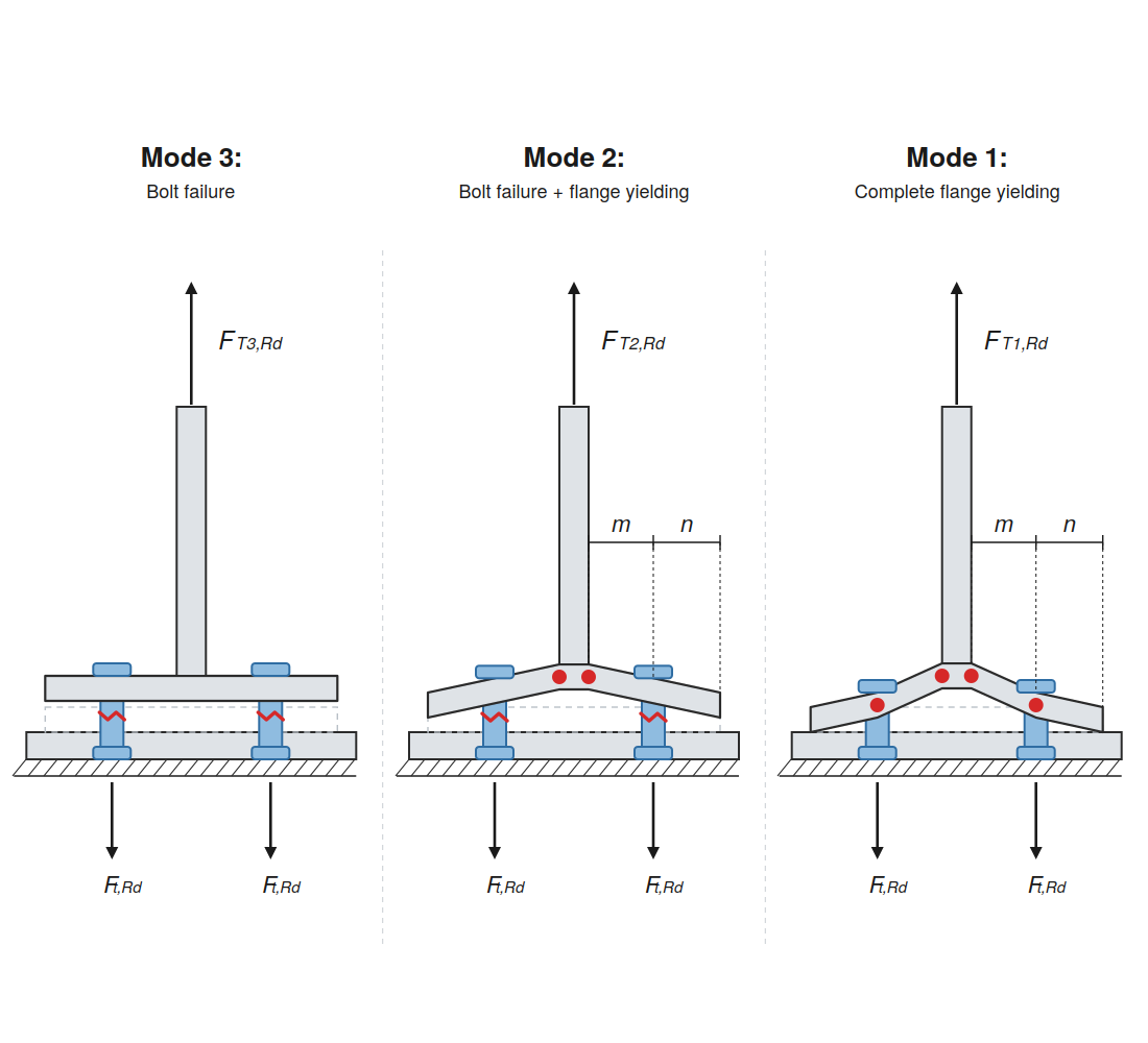
Schematic diagram illustrating the three failure modes of a T-stub connection: Mode 1 complete flange yielding, Mode 2 combined bolt failure and flange yielding, and Mode 3 pure bolt failure.
2026-06-22
063256
  • RFEM 6

Failure Modes of T-Stub

Schematic diagram illustrating the three failure modes of a T-stub connection: Mode 1 complete flange yielding, Mode 2 combined bolt failure and flange yielding, and Mode 3 pure bolt failure.

The diagram displays the three potential failure mechanisms of a T-stub connection under tension. Mode 1 represents complete flange yielding with plastic hinges forming at the flange root and bolt line. Mode 2 shows a combination of bolt failure and partial flange yielding. Mode 3 illustrates the case of pure bolt failure without significant flange deformation.
  • T-stub
  • Failure modes
  • Flange yielding
  • Bolt failure
  • Steel connection design
  • Component method
  • Eurocode 3
Used in
  • Analysis of High-Strength Steel Section and End Plate Connections with Steel Joints Add-on for RFEM
Share