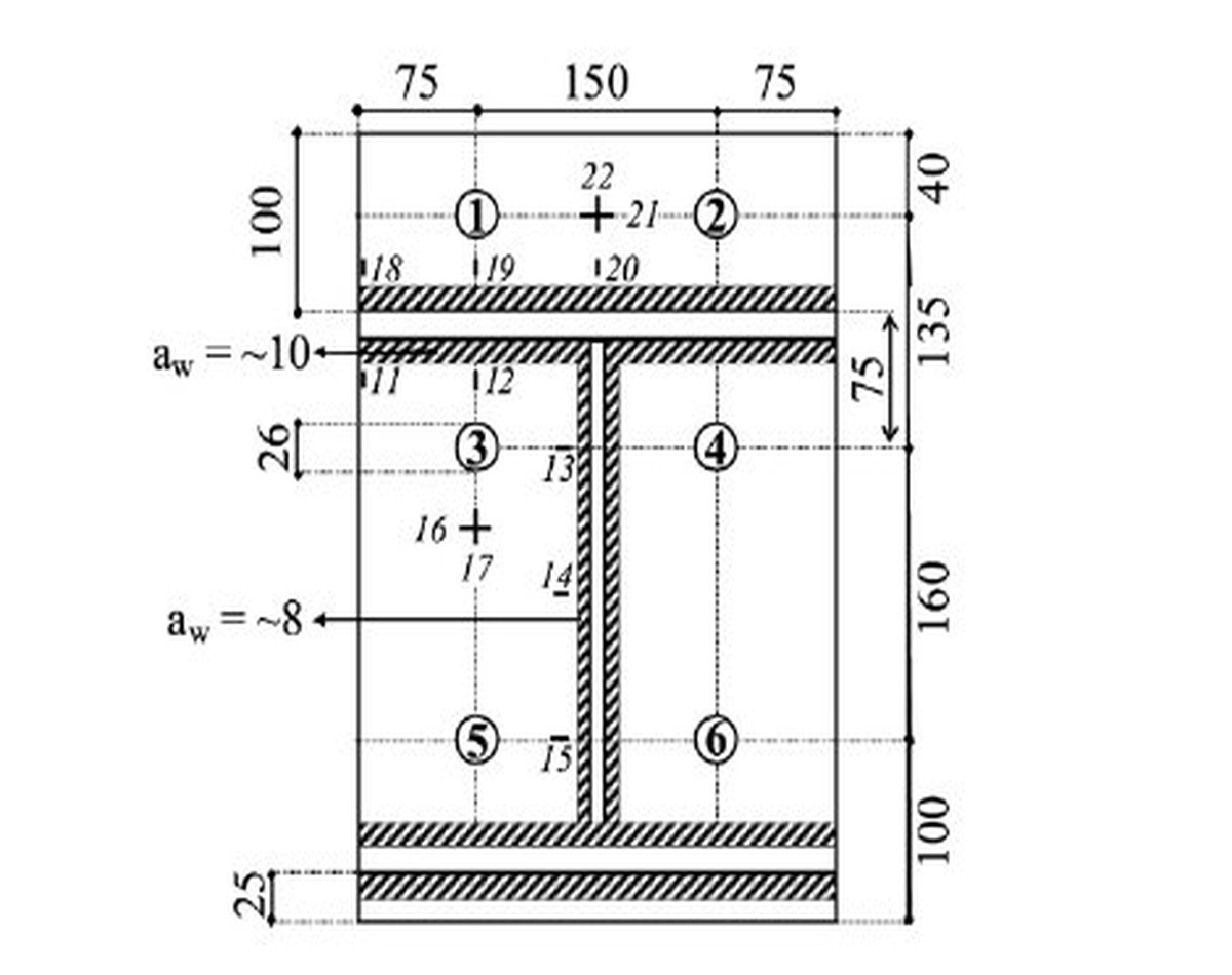
Technical diagram illustrating the end plate and bolt configuration for connection JD1, showing bolt positions, dimensions, and spacing for structural steel design.
2026-06-22
063257
  • RFEM 6

End Plate/Bolt Configuration of JD1

Technical diagram illustrating the end plate and bolt configuration for connection JD1, showing bolt positions, dimensions, and spacing for structural steel design.

Image 2 shows the end plate/bolt configuration of JD1. The diagram displays a symmetrical arrangement of six bolts with specific horizontal dimensions and vertical positions. The end plate includes two horizontal stiffeners.
  • Steel connection
  • End plate connection
  • Bolt configuration
  • Joint design
  • Structural detailing
Used in
  • Analysis of High-Strength Steel Section and End Plate Connections with Steel Joints Add-on for RFEM
Share