Subject:
Timber Beam Design per the 2014 CSA Standard
Comment:
Using the RF-TIMBER CSA module, timber beam design is possible according to the CSA O86-14 standard. Accurately calculating timber member bending resistance and adjustment factors is important for safety considerations and design. The following article will verify the factored bending moment resistance in the RFEM add-on module RF-TIMBER CSA using step-by-step analytical equations per the CSA O86-14 standard including the bending modification factors, factored bending moment resistance, and final design ratio.
Description:
Timber Beam Analysis
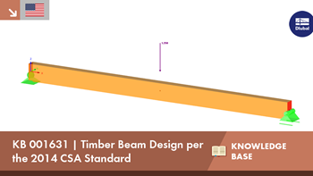
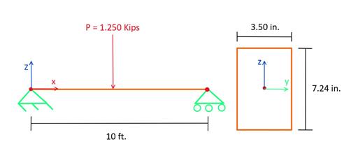
A simply supported 10 ft. long, nominal 38 mm ⋅ 89 mm Douglas Fir-Larch Structural (DF-L SS) beam with a mid-span point load of 1.250 kips will be designed. The goal of this analysis is to determine the adjusted bending factors and moment resistance of the beam. A long term load duration is assumed. Loading criteria are simplified for this example. Typical load combinations can be referenced in Sect. 5.2.4 [1]. In Figure 01, a diagram of the simple beam with loads and dimensions is shown.
Beam Properties
The cross-section used in this example is a 89 mm ⋅ 184 mm nominal dimension lumber. The actual cross-section property calculations of the sawn timber beam can be viewed below:
b = 3.50 in., d = 7.24 in., L = 10 ft.
Gross cross-section area:
A-g = b ⋅ d = (3.50 in.) ⋅ (7.24 in.) = 25.34 in.²
Section modulus:
Moment of inertia:
The material that will be used for this example is DF-L SS. The material properties are as follows.
Reference bending design value:
f-b = 2,393.12 psi
Modulus of elasticity:
E = 1,812,970 psi
Beam Modification Factors
For the design of timber members per the CSA O86 - 14 standard, modification factors must be applied to the reference bending design value (f-b). This will ultimately provide the adjusted bending design value (F-b) as well as the factored bending moment resistance (M-r).
F-b = f-b ⋅ (K-D ⋅ K-H ⋅ K-s ⋅ K-T)
Below, each modification factor is further explained and determined for this example.
K-D - The load duration factor accounts for different load periods. Snow, wind, and earthquakes loads are considered with K-D. This means K-D is dependent on the load case. In this case, K-D is set to 0.65 per Table 5.3.2.2 [1] assuming a long-term load duration.
K-S - The wet service factor considers dry or wet service conditions on sawn lumber as well as cross-section dimensions. For this example, we are assuming bending at the extreme fiber and wet service conditions. Based on Table 6.4.2 [1] K-s is equal to 0.84.
K-T - The treatment adjustment factor considers wood that has been treated with fire-retardant or other strength-reducing chemicals. This factor is determined from strength and stiffness capacities based on documented time, temperature, and moisture test. For this factor, Sect. 6.4.3 [1] is referenced. For this example, 0.95 is multiplied by the modulus of elasticity and 0.85 for all other properties when assuming wet service conditions.
K-Z - The size factor considers varying sizes of lumber and how the loading is applied to the beam. More info on this factor can be found in Sect. 6.4.5 [1]. For this example, K-Z is equal to 1.30 based on dimensions, bending and shear, and Table 6.4.5 [1].
K-H - The system factor takes into account sawn lumber members that consists of three or more essentially parallel members. These members cannot be spaced more than 610 mm apart and mutually support the load. This criteria is defined as case 1 in Sect. 6.4.4 [1]. For this example K-H is equal to 1.10 using Table 6.4.4 because we assume it as a bending member and case 1.
K-L - The lateral stability factor considers lateral supports provided along the member length which help prevent lateral displacement and rotation. The lateral stability factor (K-L) is calculated below.
Factored Specified Strength in Bending (F-B)
The factored specified strength in bending (F-b) is determined in the section below. F-b is calculated by multiplying the specified strength for bending (f-b) by the following modification factors.
K-D = 0.65
K-H = 1.10
K-s = 0.84
K-T = 0.85
We can now calculate F-b by using the following equation from Sect. 6.5.4.1 [1].
F-b = f-b ⋅ (K-D ⋅ K-H ⋅ K-s ⋅ K-T)
F-b = 1,221.71 psi
Lateral Stability Factor, K-L
The lateral stability factor (K-L) is calculated from Sect. 6.5.4.2 [1]. Before K-L can be determined, the slenderness ratio must be calculated. First, the effective length (L-e) is found in Table 7.5.6.4.3 [1]. For this beam example, a concentrated load is applied at its center with no intermediate supports. The unsupported length (l-u) is taken as 10 ft.
L-e = 1.61 (l-u)
L-e = 16.10 ft.
Then, the slenderness ratio (C-B) can be calculated based on Sect. 7.5.6.4.3 [1].
C-B = 10.69
Since t...


![RSTAB 9 results - warping moment Momega [kNm]](/en/webimage/047737/3730153/MTsec.png?mw=350&hash=40c7b896b7ecb6c898b763109dcec0b2a330f9f4)
![RSTAB 9 results - secondary torsional moment MTsec [kNm]](/en/webimage/047736/3730151/MTsec.png?mw=350&hash=40c7b896b7ecb6c898b763109dcec0b2a330f9f4)
.png?mw=512&hash=4e74affa9ad0c7b703151c5085ac9b8e59171c23)


.jpg?mw=350&hash=8f312d6c75a747d88bf9d0f5b1038595900b96c1)


.png?mw=600&hash=49b6a289915d28aa461360f7308b092631b1446e)


