Frequently Asked Questions (FAQ)
Do you have a question about the Dlubal programs? The FAQ page provides answers to frequently asked questions and commonly encountered problems. The solution is only a few clicks away! No need to wait with immediate access to hundreds of FAQ. The category filters and keyword search help you to quickly find the relevant question and answer.
2978 Results
View results:
Sort by:
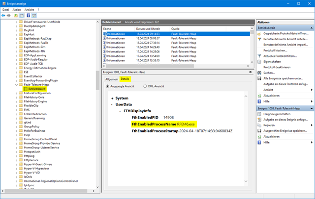
Fault Tolerant Heap (FTH)
The performance when starting the programs or working in the program has become noticeably worse. What could be the cause of this?
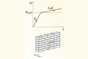
Load Extension Isotropic Masonry | Plastic
Is it possible to influence the transverse distribution of a load in the case of the Isotropic | Masonry | Plastic material model?
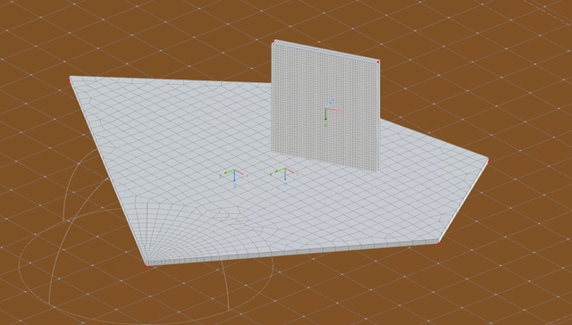
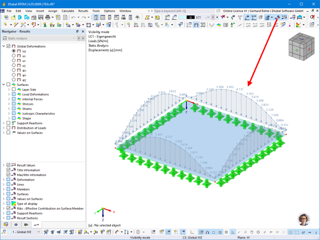
Option – Independent FE Mesh Preferred
What is the effect of the "Independent FE Mesh Ppreferred" option in the mesh settings?
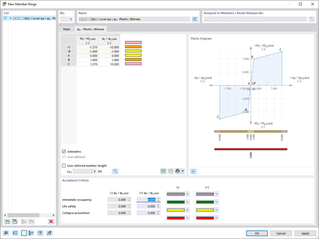
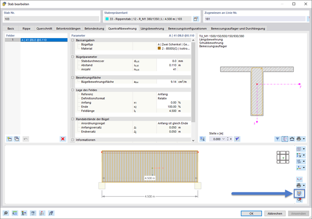
Plastic Hinges
How do I define a plastic hinge in RFEM 6?
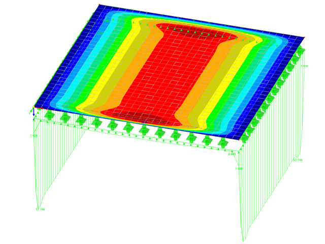
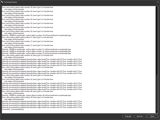
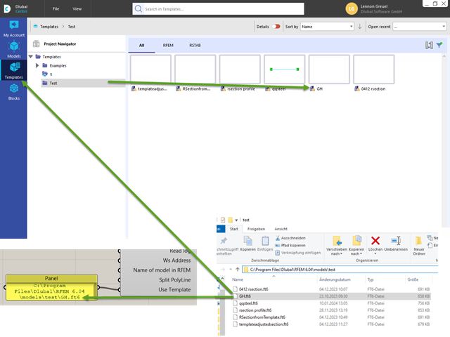
Importing Surfaces from Rhino into RFEM 6
Why are not all surfaces transferred when importing surfaces from Rhino into RFEM 6?
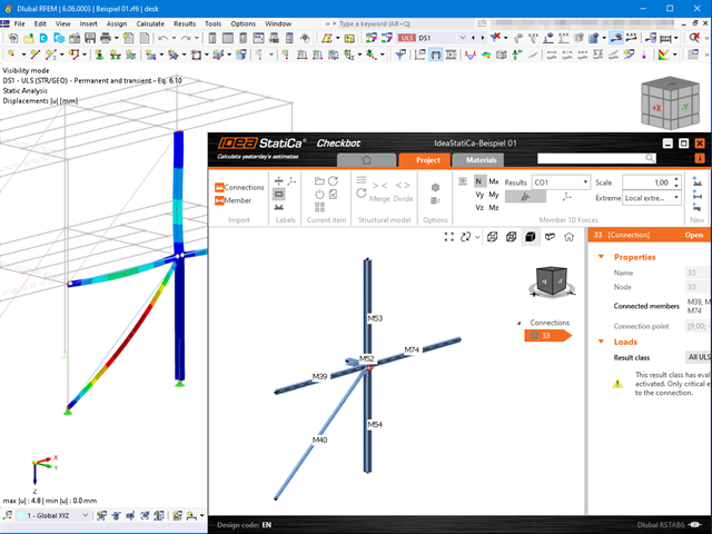
Interface RFEM 6 / RSTAB 9 – IDEA StatiCa
How can I exchange data between RFEM 6 / RSTAB 9 and IDEA StatiCa?
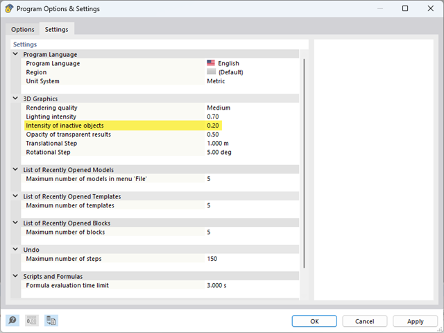
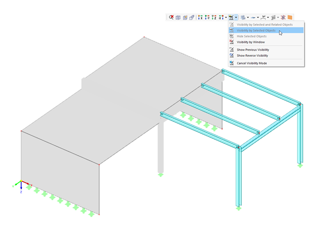
Inactive Object Intensity
How can I adjust the brightness of inactive objects?
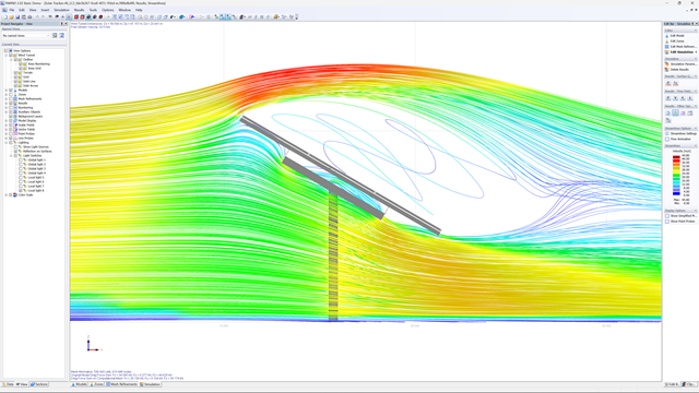
Advantages of CFD Simulation
What are the advantages of CFD simulation compared to conventional experimental tests?
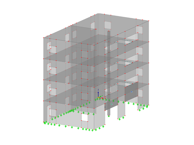
Add-ons for Concrete Structures
Which products do you recommend for the structural analysis and design of reinforced concrete structures?

Add-ons for Steel Structures
I process steel structures. Which products do you recommend for this area?
Direct vs. Iterative Solver
The calculation in RFEM 6 takes a very long time, but the processor utilization of my system is low. Why is this?
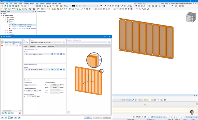
State of Development of Beam Panel
What is the current state of development of the "beam panel" element for modeling timber frame walls?
Not Valid/Deactivated Punching Nodes
In the table of the objects to be designed in the Concrete Design add-on, punching nodes are listed in the not valid/deactivated column, although I have defined them as punching nodes. How can I fix this?
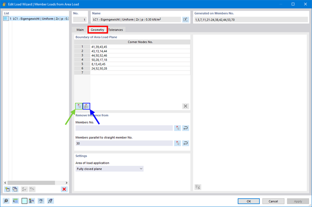
Area Loads on Members via Cells
How can I generate an area load on members via cells in RFEM 6 or RSTAB 9?
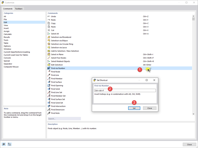
Changing Mia's Shortcut
The keyboard shortcut of the AI assistant Mia conflicts with another shortcut that I use in the system. How can I change the Mia shortcut?
Setting of I-Beam Flange Support for Design in Structure Stability Add-on
In the Steel Design add-on, I have set the boundary conditions in such a way that the I-beam flange is restrained against the horizontal displacement. I then calculated the critical load factors using the Structure Stability add-on, but with no effect on the critical load factor value. What is the reason for this?
Download Student Version
I have installed a trial version of RFEM 6 on my computer and now I want to use the student version. Where can I download the student license?