16 Wyniki
Wyświetl wyniki:
Sortuj według:

Konstrukcja składa się z swobodnie podpartej belki o przekroju dwuteowym. Obrót osiowy φx jest ograniczony na obu końcach, ale przekrój może ulec deplanacji (podpora widełkowa). Belka posiada początkową imperfekcję w kierunku Y zdefiniowaną jako krzywa paraboliczna o maksymalnym przemieszczeniu 30 mm w środku. Obciążenie równomierne zostaje przyłożone w środku górnego pasa profilu dwuteowego. Problem opisano za pomocą poniższego zestawu parametrów. Przykład obliczeniowy oparty jest na przykładzie wprowadzonym przez Gensichen i Lumpe.
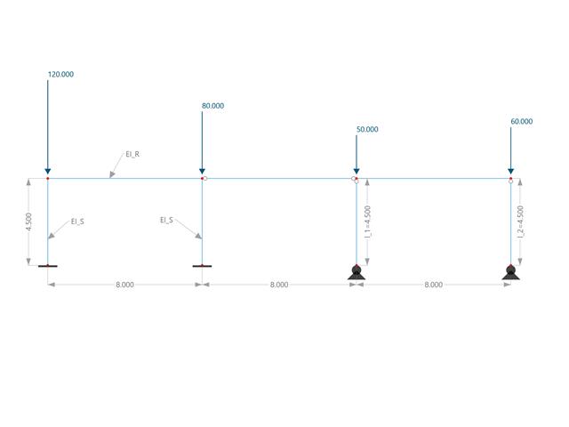
W tym przykładzie porównuje się długości efektywne i współczynnik obciążenia krytycznego, które mogą być obliczone w programie RFEM 6 przy użyciu rozszerzenia Stateczność konstrukcji, z obliczeniami ręcznymi. Układ konstrukcyjny stanowi sztywna rama z dwoma dodatkowymi słupami przegubowymi. Ten słup jest obciążany pionowymi obciążeniami skupionymi.
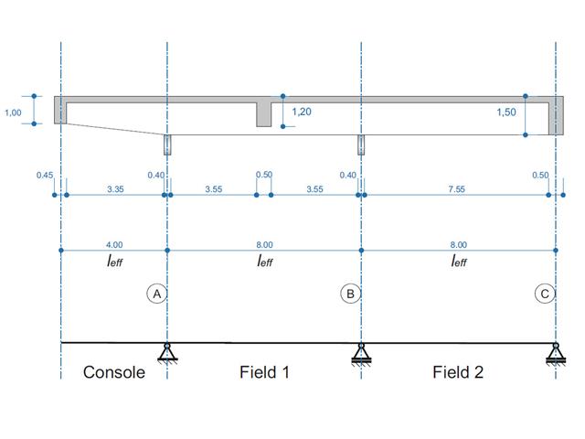
Belka żelbetowa została zaprojektowana jako belka dwuprzęsłowa na wsporniku. Przekrój zmienia się na całej długości wspornika (przekrój o zmiennym przekroju). Obliczane są siły wewnętrzne oraz wymagane zbrojenie podłużne i zbrojenie na ścinanie dla stanu granicznego nośności.
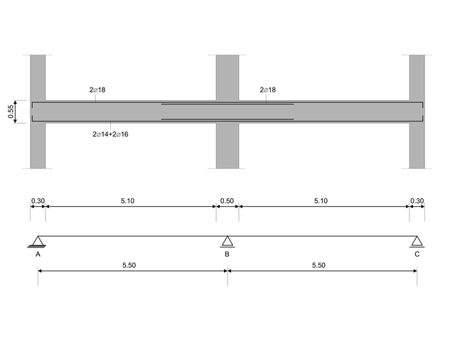
W tym przykładzie obliczeniowym obliczane są wartości nośności sił tnących na belkach zgodnie z EN 1998-1, 5.4.2.2 i 5.5.2.1 oraz nośność słupów przy zginaniu zgodnie z 5.2.3.3(2 ). System składa się z dwuprzęsłowej belki żelbetowej o rozpiętości 5,50 m. Belka jest częścią układu ramowego. Otrzymane wyniki są porównywane z wynikami w [1].
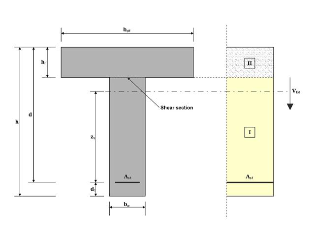
W tym przykładzie ścinanie na granicy między betonem wylanym w różnym czasie a odpowiednim zbrojeniem jest określane zgodnie z DIN EN 1992-1-1. Wyniki uzyskane w programie RFEM 6 zostaną porównane z poniższymi obliczeniami ręcznymi.
Model oparty jest na przykładzie 4 z [1]: Płyta podparta punktowo.
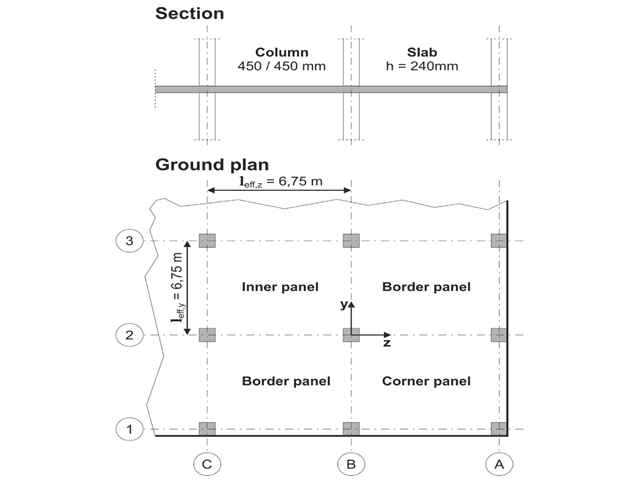
Należy zaprojektować płaską płytę budynku biurowego o wrażliwych na zarysowania ścianach lekkich. Należy zbadać panele wewnętrzne, brzegowe i narożne. Słupy i płyta są połączone monolitycznie. Słupy skrajne i narożne są zlicowane z krawędzią płyty. Osie słupów tworzą siatkę kwadratową. Jest to układ sztywny (budynek usztywniony ścianami usztywniającymi).
Budynek biurowy ma 5 kondygnacji i ma wysokość 3.000 m. Warunki środowiskowe, które należy przyjąć, określane są jako „zamknięte przestrzenie wewnętrzne”. Występują głównie oddziaływania statyczne.
Celem tego przykładu jest określenie momentów w płycie i wymaganego zbrojenia nad słupami przy pełnym obciążeniu.
Model oparty jest na przykładzie 4 z [1]: Płyta podparta punktowo. Siły wewnętrzne i wymagane zbrojenie podłużne można znaleźć w przykładzie weryfikacji 1022. W tym przykładzie przebijanie jest rozpatrywane w osi B/2.
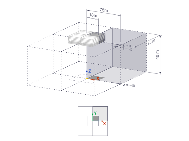
Osiadania sztywnego fundamentu kwadratowego na glinie jeziornej [1] są obliczane w programie RFEM. Modelowana jest jedna czwarta fundamentu. Fundament ma szerokość 75,0 m po obu stronach. Do wygenerowania wyników wykorzystywane są etapy budowy.
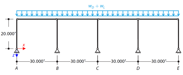
Za pomocą LRFD i ASD należy określić wymagane wytrzymałości i współczynniki długości efektywnej dla słupów z materiału ASTM A992 w ramie skręcania pokazanej na rysunku 1 dla maksymalnej kombinacji obciążeń grawitacyjnych.
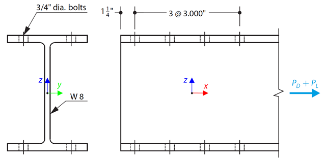
Wybrano pręt w kształcie litery W zgodny z ASTM A992 tak, aby przeniósł ciężar własny 30 000 kN i obciążenie rozciągające 90 000 kN. Sprawdź wytrzymałość pręta za pomocą LRFD i ASD.