14 Wyniki
Wyświetl wyniki:
Sortuj według:
Należy sprawdzić, czy belka o różnych przekrojach wykonana ze Stopu 6061-T6 jest odpowiednia do wymaganego obciążenia, zgodnie z Aluminium Design Manual (Podręcznik projektowania konstrukcji aluminiowych 2020).
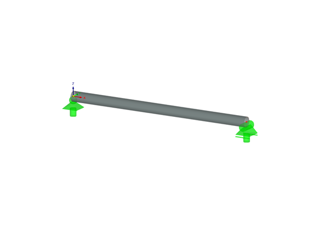
Określ dopuszczalną wytrzymałość na ściskanie osiowe belki o długości 2,2 m i przekroju różnych przekrojów, wykonanej ze stopu 6061-T6 i zabezpieczonej bocznie w celu zapobiegania wyboczeniu względem słabej osi zgodnie z Instrukcją projektowania konstrukcji aluminiowych 2020.
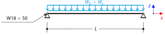
Rozważ belkę ASTM A992 W 18x50 dla stałych i równomiernych obciążeń stałych i ruchomych, jak pokazano na Rysunku 1. Pręt jest ograniczony do maksymalnej nominalnej głębokości wynoszącej 18 cali. Ugięcie pod obciążeniem użytkowym jest ograniczone do L/360. Belka jest swobodnie podparta i usztywniona. Sprawdź dostępną wytrzymałość na zginanie wybranej belki na podstawie LRFD i ASD.
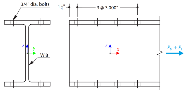
Wybrano pręt w kształcie litery W zgodny z ASTM A992 tak, aby przeniósł ciężar własny 30 000 kN i obciążenie rozciągające 90 000 kN. Sprawdź wytrzymałość pręta za pomocą LRFD i ASD.
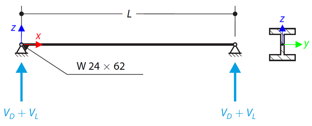
Na rysunku 1 pokazano belkę ASTM A992 W 24x62 o skróceniu do ścinania na końcu 48 000 i 145 000 kips od obciążeń stałych i użytkowych, odpowiednio Sprawdź dostępną wytrzymałość na ścinanie wybranej belki na podstawie LRFD i ASD.
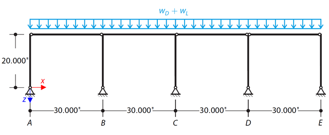
Za pomocą LRFD i ASD należy określić wymagane wytrzymałości i współczynniki długości efektywnej dla słupów z materiału ASTM A992 w ramie skręcania pokazanej na rysunku 1 dla maksymalnej kombinacji obciążeń grawitacyjnych.
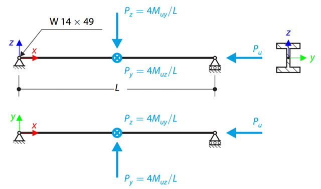
Korzystając z tabel ręcznych AISC, należy określić dostępne wytrzymałości na ściskanie i zginanie oraz czy belka ASTM A992 W14x99 ma wystarczającą wytrzymałość, aby przenieść siły osiowe i momenty pokazane na rysunku 1, uzyskane w analizie drugiego rzędu z uwzględnieniem efektów P-𝛿.
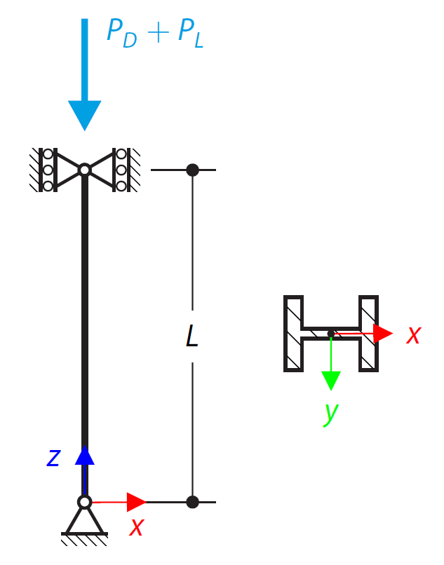
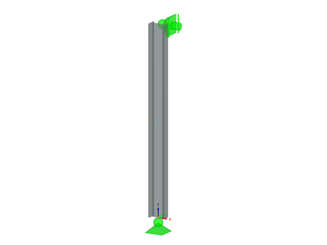
Słup w kształcie litery W zgodny z normą ASTM A992 14x132 jest obciążony zadanymi osiowymi siłami ściskającymi. Słup jest przegubowy na górze i na dole w obu osiach. Należy określić, czy słup jest w stanie wytrzymać obciążenie pokazane na rysunku 1 na podstawie LRFD i ASD.
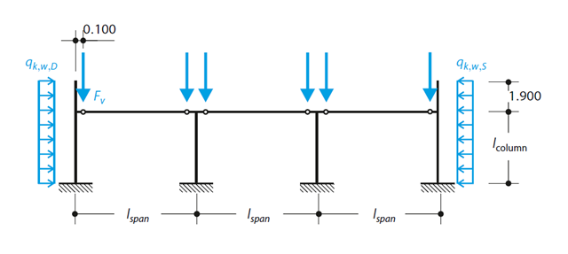
Zgodnie z DIN EN 1992-1-1/NA/A1:2015, na podstawie 1990-1-1/NA/A1:2012-08 słup z betonu zbrojonego jest projektowany pod kątem SGN w temperaturze normalnej. W obliczeniach zastosowano metodę krzywizny nominalnej; patrz DIN EN 1992-1-1, rozdział 5.8.8. Zaadresowany słup znajduje się na krawędzi trzyprzęsłowej konstrukcji ramowej, która składa się z 4 słupów wspornikowych i 3 pojedynczych kratownic połączonych przegubowo z nimi. Na słup działa siła pionowa prefabrykowanej kratownicy, śnieg i wiatr. Wyniki porównano z literaturą.
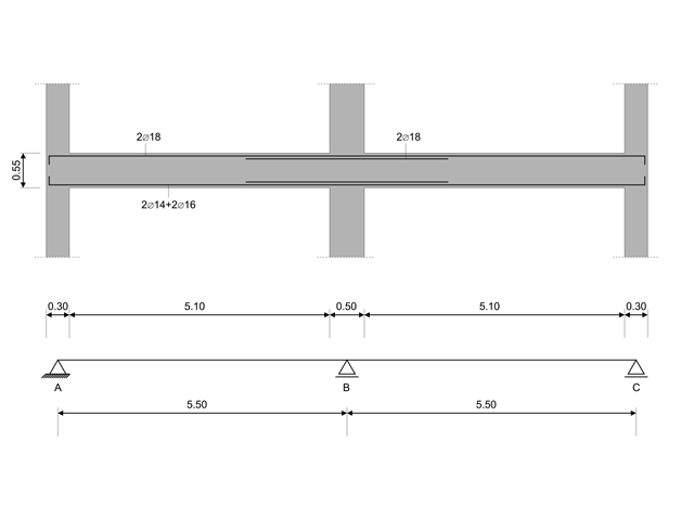
W tym przykładzie obliczeniowym obliczane są wartości nośności sił tnących na belkach zgodnie z EN 1998-1, 5.4.2.2 i 5.5.2.1 oraz nośność słupów przy zginaniu zgodnie z 5.2.3.3(2 ). System składa się z dwuprzęsłowej belki żelbetowej o rozpiętości 5,50 m. Belka jest częścią układu ramowego. Otrzymane wyniki są porównywane z wynikami w [1].