18 Wyniki
Wyświetl wyniki:
Sortuj według:

W tym przykładzie weryfikacyjnym sprawdzana jest nośność wewnętrznego słupa płyty płaskiej na ścinanie. Słup ma przekrój kołowy o średnicy 30 cm.
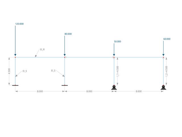
W tym przykładzie porównuje się długości efektywne i współczynnik obciążenia krytycznego, które mogą być obliczone w programie RFEM 6 przy użyciu rozszerzenia Stateczność konstrukcji, z obliczeniami ręcznymi. Układ konstrukcyjny stanowi sztywna rama z dwoma dodatkowymi słupami przegubowymi. Ten słup jest obciążany pionowymi obciążeniami skupionymi.
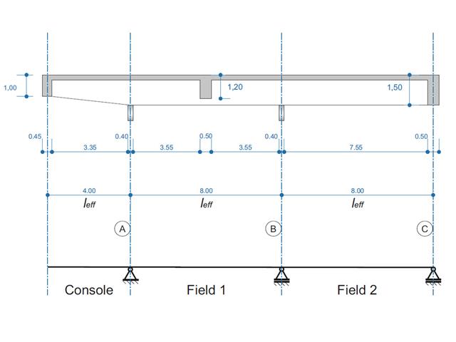
Belka żelbetowa została zaprojektowana jako belka dwuprzęsłowa na wsporniku. Przekrój zmienia się na całej długości wspornika (przekrój o zmiennym przekroju). Obliczane są siły wewnętrzne oraz wymagane zbrojenie podłużne i zbrojenie na ścinanie dla stanu granicznego nośności.
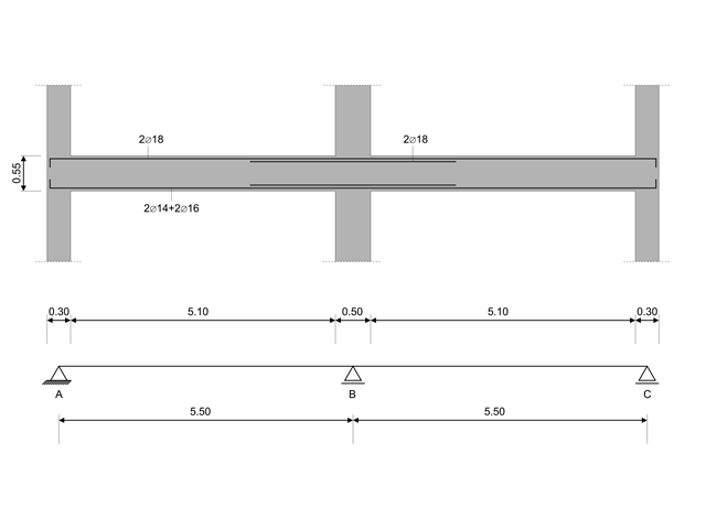
W tym przykładzie obliczeniowym obliczane są wartości nośności sił tnących na belkach zgodnie z EN 1998-1, 5.4.2.2 i 5.5.2.1 oraz nośność słupów przy zginaniu zgodnie z 5.2.3.3(2 ). System składa się z dwuprzęsłowej belki żelbetowej o rozpiętości 5,50 m. Belka jest częścią układu ramowego. Otrzymane wyniki są porównywane z wynikami w [1].
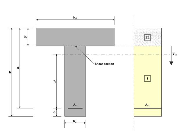
W tym przykładzie ścinanie na granicy między betonem wylanym w różnym czasie a odpowiednim zbrojeniem jest określane zgodnie z DIN EN 1992-1-1. Wyniki uzyskane w programie RFEM 6 zostaną porównane z poniższymi obliczeniami ręcznymi.
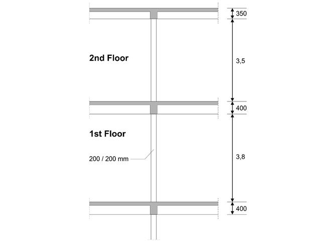
W pierwszym piętrze budynku zaprojektowano słup wewnętrzny. Słup jest monolityczny, połączony z belką górną i dolną. Uproszczona metoda A obliczeń odporności ogniowej dla słupów zgodnie z EC2-1-2 została potwierdzona, a wyniki porównane z [1].
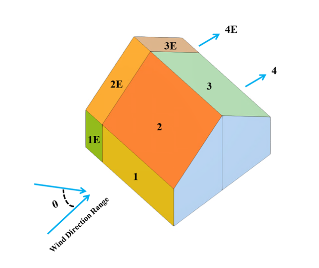
W bieżącym przykładzie walidacyjnym badany jest współczynnik ciśnienia wiatru (Cp) zarówno dla głównych elementów konstrukcyjnych (Cp,ave ), jak i drugorzędnych elementów konstrukcyjnych, takich jak systemy okładziny lub fasady (Cp,local ) w oparciu o NBC 2020 [1] and Baza danych japońskich tuneli aerodynamicznych dla niskiego budynku o nachyleniu 45 stopni. Zalecane ustawienie dla trójwymiarowego dachu płaskiego z ostrym okapem zostanie opisane w następnej części.
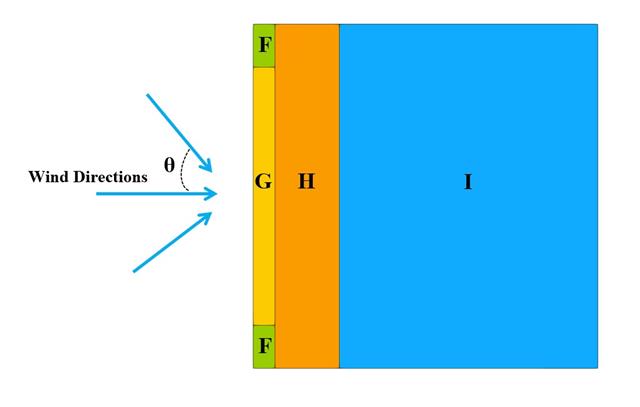
W poniższym przykładzie sprawdzamy wartość ciśnienia wiatru zarówno dla ogólnego projektowania konstrukcyjnego (Cp,10 ), jak i lokalnego projektowania konstrukcyjnego, takiego jak okładziny lub fasady (Cp,1 ) w oparciu o EN 1991-1-4, przykład dachu płaskiego [1] and Baza danych japońskich tuneli aerodynamicznych . Zalecane ustawienie dla trójwymiarowego dachu płaskiego z ostrym okapem zostanie opisane w następnej części.
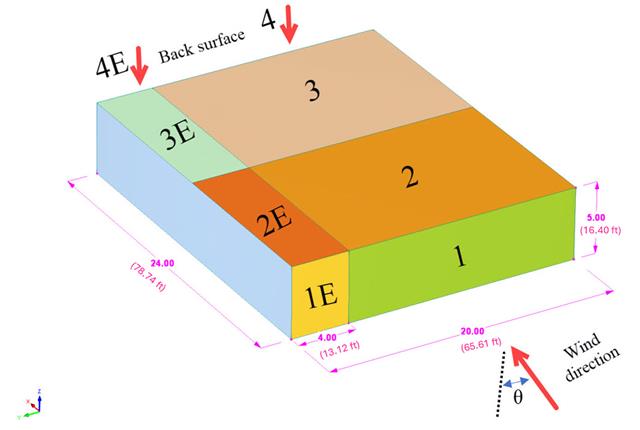
W bieżącym przykładzie walidacyjnym badamy współczynnik parcia wiatru (Cp) płaskiego dachu i ścian za pomocą ASCE7-22 [1]. W rozdziale 28.3 (Obciążenia wiatrem - główny układ odporności na siłę wiatru) i na Rysunku 28.3-1 (przypadek obciążenia 1) znajduje się tabela przedstawiająca wartość Cp dla różnych kątów nachylenia dachu.
Model oparty jest na przykładzie 4 z [1]: Płyta podparta punktowo.
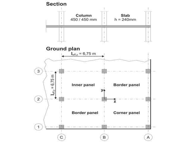
Należy zaprojektować płaską płytę budynku biurowego o wrażliwych na zarysowania ścianach lekkich. Należy zbadać panele wewnętrzne, brzegowe i narożne. Słupy i płyta są połączone monolitycznie. Słupy skrajne i narożne są zlicowane z krawędzią płyty. Osie słupów tworzą siatkę kwadratową. Jest to układ sztywny (budynek usztywniony ścianami usztywniającymi).
Budynek biurowy ma 5 kondygnacji i ma wysokość 3.000 m. Warunki środowiskowe, które należy przyjąć, określane są jako „zamknięte przestrzenie wewnętrzne”. Występują głównie oddziaływania statyczne.
Celem tego przykładu jest określenie momentów w płycie i wymaganego zbrojenia nad słupami przy pełnym obciążeniu.
Model oparty jest na przykładzie 4 z [1]: Płyta podparta punktowo. Siły wewnętrzne i wymagane zbrojenie podłużne można znaleźć w przykładzie weryfikacji 1022. W tym przykładzie przebijanie jest rozpatrywane w osi B/2.
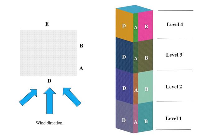
W bieżącym przykładzie walidacji badamy wartość parcia wiatru dla obu ogólnych projektów konstrukcyjnych (Cp,10 ) i okładzin lub elewacji (Cp,1 ) budynków na planie prostokąta zgodnie z EN 1991-1-4 [1]. Istnieją przypadki trójwymiarowe, o których więcej wyjaśnimy w następnej części.
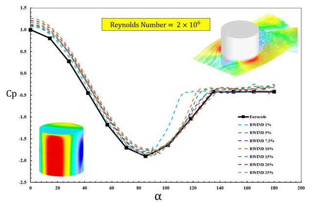
W dostępnych normach, takich jak EN 1991-1-4 [1], ASCE/SEI 7-16 i NBC 2015, przedstawiono parametry obciążenia wiatrem, takie jak współczynnik parcia wiatru (Cp ) dla podstawowe kształty. Ważne jest, jak szybciej i dokładniej obliczać parametry obciążenia wiatrem, niż pracować na czasochłonnych i czasami skomplikowanych wzorach w normach.
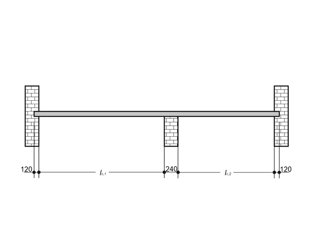
Płytę żelbetową wewnątrz budynku należy projektować jako pas o długości 1,0 m wraz z prętami. Płyta stropowa jest jednoosiowo rozpięta i przebiega przez dwa przęsła. Płyta jest mocowana do ścian murowanych za pomocą podpór swobodnie obracających się. Podpora środkowa ma szerokość 240 mm, a dwie podpory krawędziowe mają szerokość 120 mm. Oba przęsła są poddane obciążeniu użytkowemu kategorii C: obszary zborów.
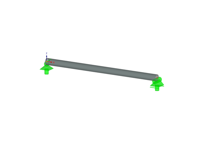
Należy sprawdzić, czy belka o różnych przekrojach wykonana ze Stopu 6061-T6 jest odpowiednia do wymaganego obciążenia, zgodnie z Aluminium Design Manual (Podręcznik projektowania konstrukcji aluminiowych 2020).
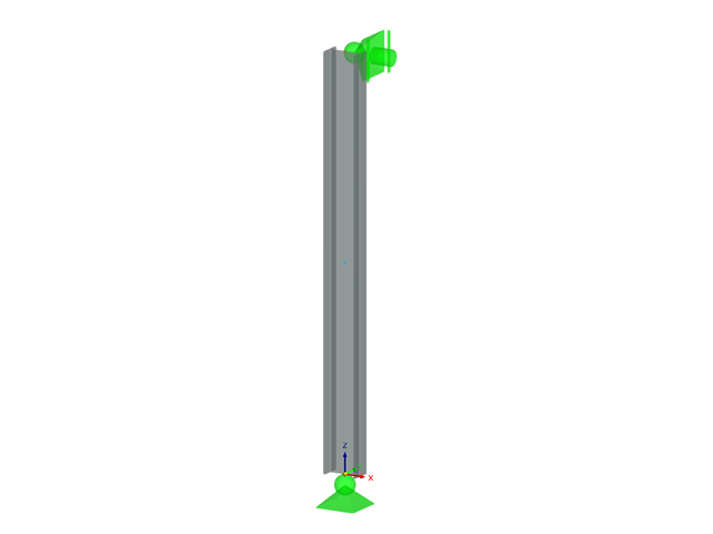
Określ dopuszczalną wytrzymałość na ściskanie osiowe belki o długości 2,2 m i przekroju różnych przekrojów, wykonanej ze stopu 6061-T6 i zabezpieczonej bocznie w celu zapobiegania wyboczeniu względem słabej osi zgodnie z Instrukcją projektowania konstrukcji aluminiowych 2020.
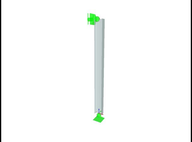
Określ dopuszczalną wytrzymałość na ściskanie osiowe belki o długości 2,2 m i przekroju różnych przekrojów, wykonanej ze stopu 6061-T6 i zabezpieczonej bocznie w celu zapobiegania wyboczeniu względem słabej osi zgodnie z Instrukcją projektowania konstrukcji aluminiowych 2020.
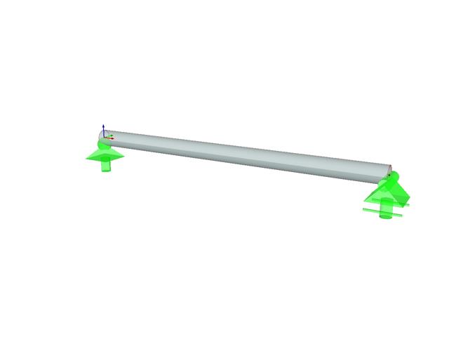
Należy sprawdzić, czy belka o różnych przekrojach wykonana ze Stopu 6061-T6 jest odpowiednia do wymaganego obciążenia, zgodnie z Aluminium Design Manual (Podręcznik projektowania konstrukcji aluminiowych 2020).