13 Wyniki
Wyświetl wyniki:
Sortuj według:
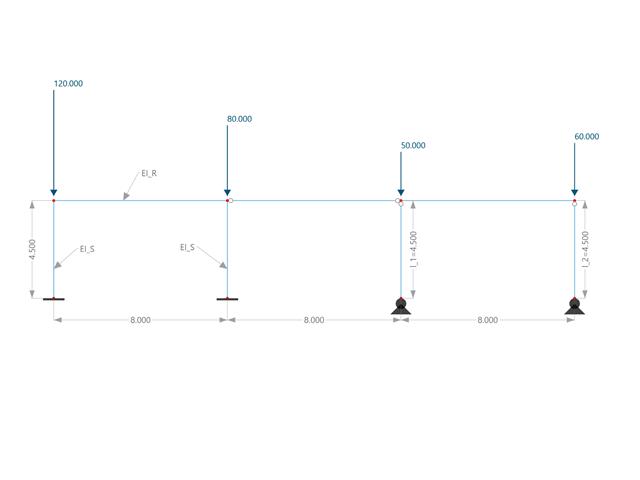
W tym przykładzie porównuje się długości efektywne i współczynnik obciążenia krytycznego, które mogą być obliczone w programie RFEM 6 przy użyciu rozszerzenia Stateczność konstrukcji, z obliczeniami ręcznymi. Układ konstrukcyjny stanowi sztywna rama z dwoma dodatkowymi słupami przegubowymi. Ten słup jest obciążany pionowymi obciążeniami skupionymi.
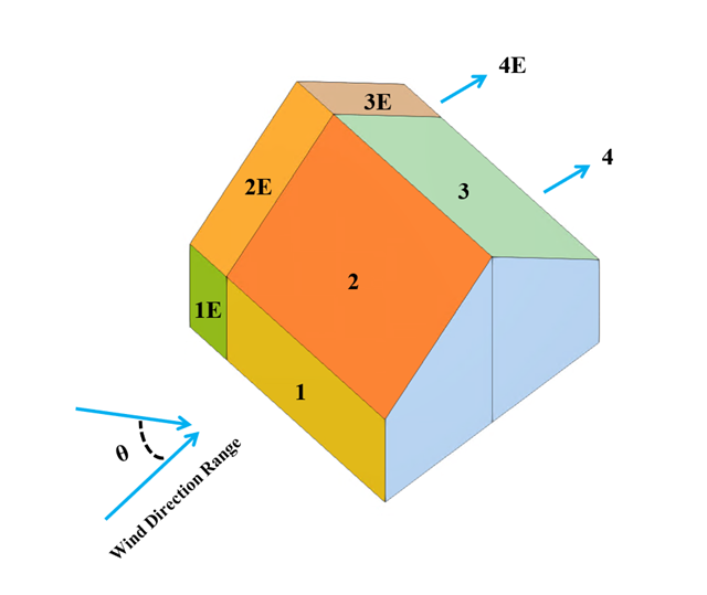
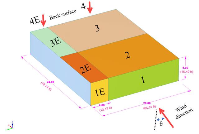
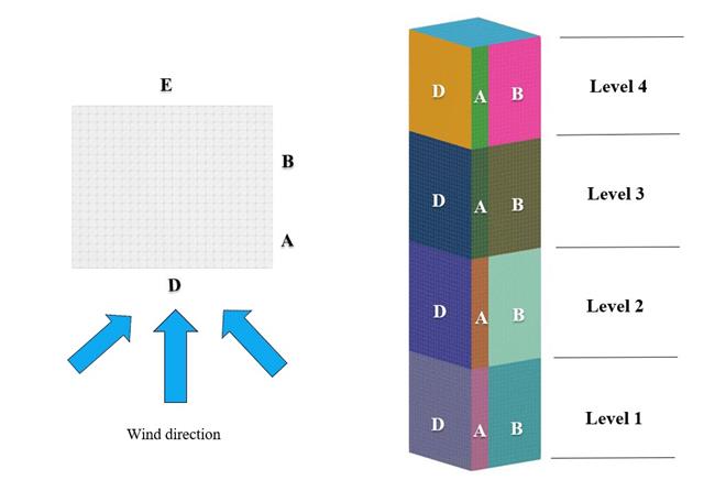
W bieżącym przykładzie walidacyjnym badany jest współczynnik ciśnienia wiatru (Cp) zarówno dla głównych elementów konstrukcyjnych (Cp,ave ), jak i drugorzędnych elementów konstrukcyjnych, takich jak systemy okładziny lub fasady (Cp,local ) w oparciu o NBC 2020 [1] and Baza danych japońskich tuneli aerodynamicznych dla niskiego budynku o nachyleniu 45 stopni. Zalecane ustawienie dla trójwymiarowego dachu płaskiego z ostrym okapem zostanie opisane w następnej części.
W poniższym przykładzie sprawdzamy wartość ciśnienia wiatru zarówno dla ogólnego projektowania konstrukcyjnego (Cp,10 ), jak i lokalnego projektowania konstrukcyjnego, takiego jak okładziny lub fasady (Cp,1 ) w oparciu o EN 1991-1-4, przykład dachu płaskiego [1] and Baza danych japońskich tuneli aerodynamicznych . Zalecane ustawienie dla trójwymiarowego dachu płaskiego z ostrym okapem zostanie opisane w następnej części.
W bieżącym przykładzie walidacyjnym badamy współczynnik parcia wiatru (Cp) płaskiego dachu i ścian za pomocą ASCE7-22 [1]. W rozdziale 28.3 (Obciążenia wiatrem - główny układ odporności na siłę wiatru) i na Rysunku 28.3-1 (przypadek obciążenia 1) znajduje się tabela przedstawiająca wartość Cp dla różnych kątów nachylenia dachu.
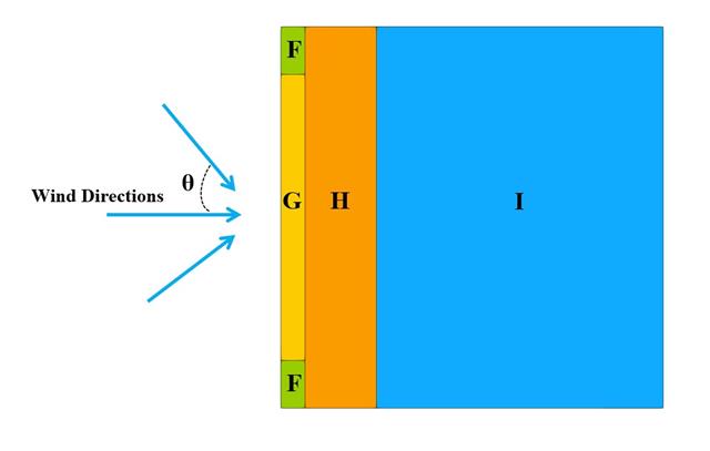
W bieżącym przykładzie walidacji badamy wartość parcia wiatru dla obu ogólnych projektów konstrukcyjnych (Cp,10 ) i okładzin lub elewacji (Cp,1 ) budynków na planie prostokąta zgodnie z EN 1991-1-4 [1]. Istnieją przypadki trójwymiarowe, o których więcej wyjaśnimy w następnej części.
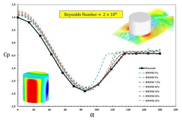
W dostępnych normach, takich jak EN 1991-1-4 [1], ASCE/SEI 7-16 i NBC 2015, przedstawiono parametry obciążenia wiatrem, takie jak współczynnik parcia wiatru (Cp ) dla podstawowe kształty. Ważne jest, jak szybciej i dokładniej obliczać parametry obciążenia wiatrem, niż pracować na czasochłonnych i czasami skomplikowanych wzorach w normach.
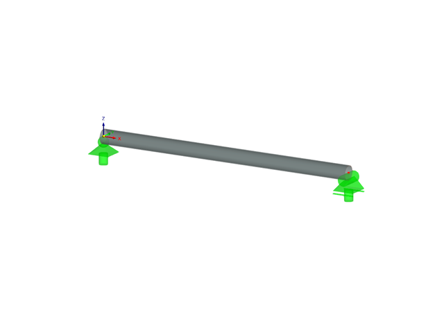
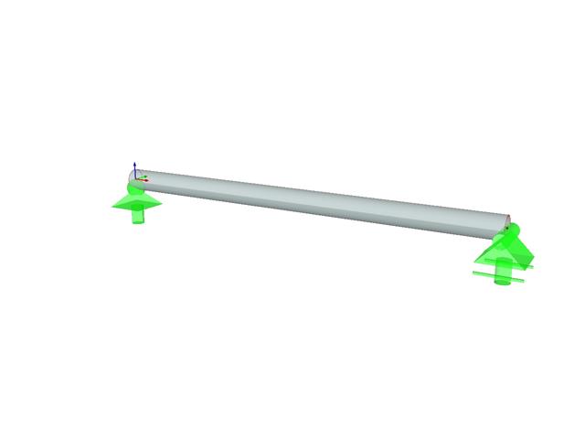
Należy sprawdzić, czy belka o różnych przekrojach wykonana ze Stopu 6061-T6 jest odpowiednia do wymaganego obciążenia, zgodnie z Aluminium Design Manual (Podręcznik projektowania konstrukcji aluminiowych 2020).
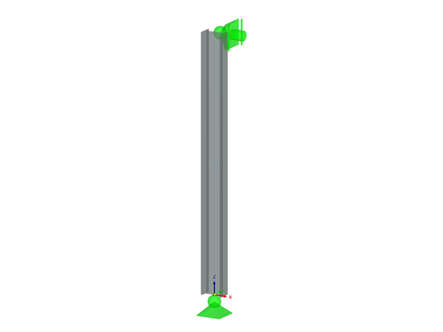
Określ dopuszczalną wytrzymałość na ściskanie osiowe belki o długości 2,2 m i przekroju różnych przekrojów, wykonanej ze stopu 6061-T6 i zabezpieczonej bocznie w celu zapobiegania wyboczeniu względem słabej osi zgodnie z Instrukcją projektowania konstrukcji aluminiowych 2020.
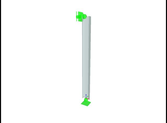
Określ dopuszczalną wytrzymałość na ściskanie osiowe belki o długości 2,2 m i przekroju różnych przekrojów, wykonanej ze stopu 6061-T6 i zabezpieczonej bocznie w celu zapobiegania wyboczeniu względem słabej osi zgodnie z Instrukcją projektowania konstrukcji aluminiowych 2020.
Należy sprawdzić, czy belka o różnych przekrojach wykonana ze Stopu 6061-T6 jest odpowiednia do wymaganego obciążenia, zgodnie z Aluminium Design Manual (Podręcznik projektowania konstrukcji aluminiowych 2020).
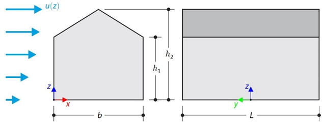
Ten przykład weryfikacyjny porównuje obliczenia obciążenia wiatrem budynku z dachem dwuspadowym, z wykorzystaniem normy ASCE 7-16, z symulacją CFD w RWIND Simulation. The building is defined according to the sketch and the inflow velocity profile taken from the ASCE 7-16 standard.
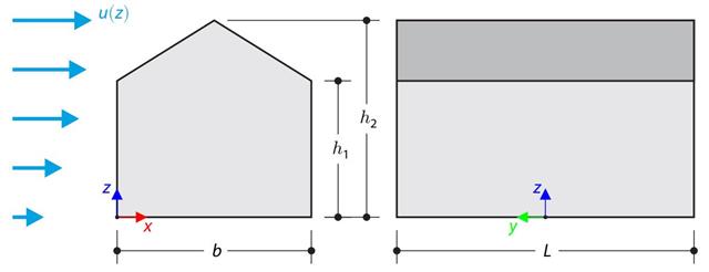
W przykładzie obliczeniowym porównano obliczenia obciążenia wiatrem budynku z dachem dwuspadowym, przeprowadzone zgodnie z normą EN 1991-1-4, z wykorzystaniem symulacji CFD w RWIND Simulation. The building is defined according to the sketch, and the inflow velocity profile is taken according to the standard EN 1991-1-4.
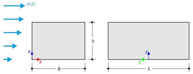
W przykładzie obliczeniowym porównano obliczenia obciążenia wiatrem budynku z płaskim dachem zgodnie z normą EN 1991-1-4 z wykorzystaniem symulacji CFD w RWIND Simulation. The building is defined according to the sketch, and the inflow velocity profile is taken according to the standard EN 1991-1-4.