21 Wyniki
Wyświetl wyniki:
Sortuj według:

Zarówno analiza drgań własnych, jak i analiza spektrum odpowiedzi przeprowadzane są na układzie liniowym. Jeżeli w modelu występują nieliniowości, podlega on linearyzacji, dzięki czemu elementy nieliniowe nie są brane pod uwagę w dalszej analizie. Mogą to być na przykład pręty rozciągane, podpory nieliniowe lub przeguby nieliniowe. W tym artykule pokazano, w jaki sposób można nimi zarządzać w analizie dynamicznej.
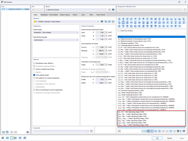
Aby umożliwić ocenę wpływu lokalnych zjawisk stateczności smukłych elementów, w programach RFEM 6 i RSTAB 9 można przeprowadzić liniową analizę obciążenia krytycznego na poziomie przekroju. Poniższy artykuł poświęcony jest podstawom obliczeń i interpretacji wyników.

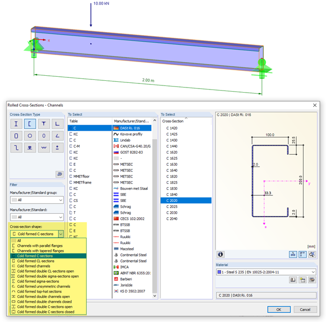
Wymiarowanie prętów stalowych formowanych na zimno zgodnie z AISI S100-16 jest teraz dostępne w programie RFEM 6. Design can be accessed by selecting “AISC 360” as the standard in the Steel Design add-on. “AISI S100” is then automatically selected for the cold-formed design (Image 01).

Zaletą modułu dodatkowego RFEM 6 Steel Joints jest możliwość analizy połączeń stalowych przy użyciu modelu MES, dla którego modelowanie przebiega w pełni automatycznie w tle. Elementy składowe złącza stalowego, które kontrolują modelowanie, można wprowadzić, definiując je ręcznie lub korzystając z dostępnych szablonów w bibliotece. Ta ostatnia metoda została opisana w poprzednim artykule z Bazy wiedzy zatytułowanym „Definiowanie komponentów połączenia stalowego przy użyciu biblioteki”. Definiowanie parametrów do wymiarowania połączeń stalowych jest tematem artykułu w bazie wiedzy „Projektowanie połączeń stalowych w RFEM 6”.
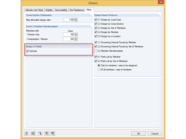
Das Zusatzmodul RF-/STAHL EC3 kann den Nachweis der Halskehlnähte für alle parametrischen, geschweißten Querschnitte der Querschnittsbibliothek führen. Hierzu muss die Option in den Detaileinstellungen des Moduls aktiviert werden. Alternativ kann auch ein Flächenmodell zur Bemessung genutzt werden.
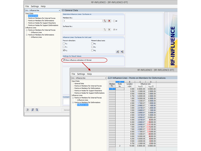
Standardmäßig werden die ermittelten Werte für die Ordinaten der Einflusslinie als Dezimalzahl mit maximal sechs Nachkommastellen ausgegeben. Für die Einflusslinien der Schnittgrößen ist dies meist ausreichend.
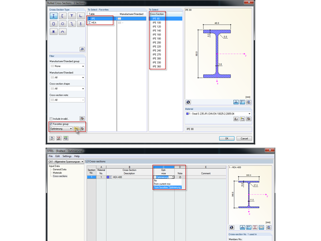
Bei der Querschnittsoptimierung in den Zusatzmodulen können auch beliebig definierte Querschnitts-Favoritenlisten ausgewählt werden - zusätzlich zu den Profilen aus der gleichen Profilreihe wie das ursprüngliche Profil.
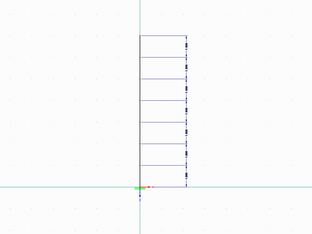
Mit RF-/DYNAM Pro Ersatzlasten ist es möglich, eine Ersatzlastberechnung anhand des multimodalen Antwortspektren-Verfahrens zu durchzuführen. Im dargestellten Beispiel wurde dies für einen Mehrmassenschwinger durchgeführt.
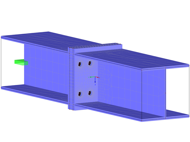
Projektowanie sztywnych połączeń z blachami czołowymi jest szczególnie skomplikowane w przypadku geometrii połączeń gdzie występują cztery łączniki w jednym rzędzie oraz dwukierunkowe zginanie, ponieważ nie istnieją oficjalne wytyczne do wymiarowania tego typu detali.
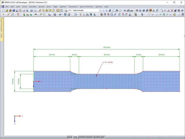
Deformacje sprężyste elementu konstrukcyjnego pod wpływem obciążenia są oparte na prawie Hooke'a, opisującym liniową zależność naprężenie-odkształcenie. Są one odwracalne: po odciążeniu element powraca do swojego pierwotnego kształtu. Jednakże deformacje plastyczne są nieodwracalne i zazwyczaj znacznie większe niż odkształcenia sprężyste. W przypadku naprężeń plastycznych materiałów ciągliwych, takich jak stal, efekty plastyczności występują w miejscach, w których wzrostowi odkształceń towarzyszy zjawisko lokalnego wzmocnienia. Prowadzi to do powstania trwałych deformacji, a w ekstremalnych przypadkach do zniszczenia elementu konstrukcyjnego.
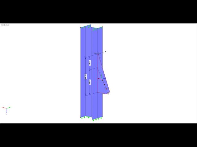
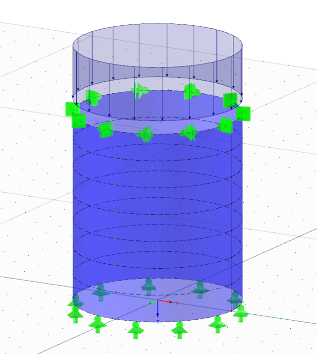
Europejska norma EN 1993-1-8, sekcja 4.5.3.3. umożliwia zastosowanie uproszczonej metody obliczania stanu granicznego nośności spoin pachwinowych. Zgodnie z normą warunki nośności można uznać za spełnione, jeżeli wartość obliczeniowa wypadkowej oddziałującej na obszar spoiny pachwinowej jest mniejsza niż wartość obliczeniowa nośności spoiny. Jeśli więc wymiarowanie spoiny ma zostać przeprowadzone na bazie wyników z modelu powierzchniowego, użytkownik może odczytać liczne typy rezultatów ze względu na charakter obliczeń MES dla powłok. Dlatego w tym artykule pokazujemy, jak określić składowe siły z takiego modelu.
Zgodnie z punktem 3.2.2 normy EN 1993-1-3 możliwe jest zastosowanie podwyższonej średniej granicy plastyczności fya dla przekrojów poprzecznych tam, gdzie dochodzi do efektu dosztywnienia w wyniku powstałego odkształcenia (tzw. strain hardening).
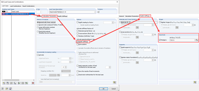
Zarówno analiza drgań własnych, jak i analiza spektrum odpowiedzi przeprowadzane są na układzie liniowym. Jeżeli w modelu występują nieliniowości, podlega on linearyzacji, dzięki czemu elementy nieliniowe nie są brane pod uwagę w dalszej analizie. W praktyce jednak bardzo często wprowadzamy do modeli elementy "tylko rozciągane". W przedstawionym artykule opisano, w jaki sposób można je poprawnie zastąpić dla przeprowadzenia liniowej analizy dynamicznej.
Zasady obliczania stalowych elementów walcowanych na zimno są zdefiniowane w EN 1993-1-3. Typowe kształty przekrojów formowanych na zimno to: ceowniki, zetowniki, kształtowniki kapeluszowe lub sigma. Są to wyroby stalowe wykonywane z cienkich blach w procesie walcowania na zimno lub gięcia. Podczas obliczania stanów granicznych nośności należy dopilnować, aby lokalne siły poprzeczne nie prowadziły w środniku do ściskania, wybrzuszenia, wyboczenia lub innej lokalnej formy utraty stateczności. Efekty te mogą być spowodowane działaniem lokalnych sił poprzecznych na półkę profilu oraz sił reakcji w punktach podparcia. W sekcji 6.1.7 normy EN 1993-1-3 szczegółowo opisano, jak określić nośność środnika Rw, Rd na wpływ działania lokalnych sił poprzecznych.
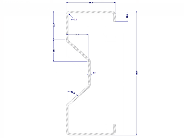
Obliczenia stanu granicznego nośności przekrojów formowanych na zimno zgodnie z EN 1993-1-3 i EN 1993-1-5 można przeprowadzić za pomocą rozszerzenia RF-/STEEL Cold-Formed Sections. Oprócz profili formowanych na zimno z bazy danych przekrojów, SHAPE-THIN umożliwia także obliczanie przekrojów uogólnionych.
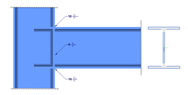
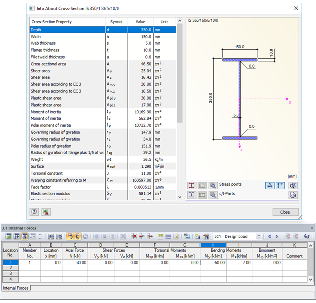
Bemessung einer geschweißten Verbindung eines HEA-Profils unter zweiachsiger Biegung mit Normalkraft. Nachweis der Schweißnähte für die gegebenen Schnittgrößen nach dem vereinfachten Verfahren (DIN EN 1993-1-8 Abs. 4.5.3.3 ) mittels DUENQ.
Beim Nachweis eines Stahlquerschnitts nach Eurocode 3 ist die Zuordnung des Profils zu einer der vier Querschnittsklassen entscheidend. Die Klassen 1 und 2 ermöglichen eine plastische Bemessung, für die Klassen 3 und 4 sind nur elastische Nachweise zulässig. Neben der Beanspruchbarkeit des Querschnitts ist die ausreichende Stabilität des Bauteils nachzuweisen.
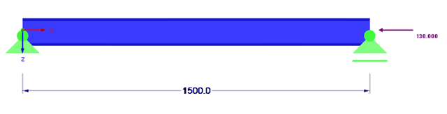
Poniższy artykuł opisuje sposób przeprowadzania obliczeń belki dwuprzęsłowej, poddanej zginaniu, z zastosowaniem modułu dodatkowego RF-/STEEL EC3 zgodnie z EN 1993-1-1. Globalne zakłócenie stateczności zostanie wykluczone, dzięki zastosowaniu dostatecznych środków zapewniających stateczność.
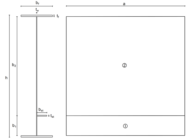
W SHAPE-THIN, obliczenia użebrowanych paneli wyboczeniowych można przeprowadzić zgodnie z sekcją 4.5 normy EN 1993-1-5. W przypadku wyboczenia usztywnionego panelu należy uwzględnić powierzchnie efektywne od lokalnego wyboczenia poszczególnych paneli w płycie i usztywnieniach oraz powierzchnie efektywne całego wyboczenia całego panelu.
Das Schalenbeulen gilt als das jüngste und am wenigsten erforschte Stabilitätsproblem der Bautechnik. Dies liegt weniger an mangelnden Forschungsaufwendungen, sondern vielmehr an der Komplexität der Theorie. Mit der Einführung und Fortentwicklung der Finite-Elemente-Methode in der bautechnischen Praxis erscheint es manchem Ingenieur nicht mehr erforderlich, sich mit der komplizierten Theorie des Schalenbeulens auseinanderzusetzen. Zu welchen Problemen und Fehlern dies führen kann, ist in [1] sehr gut zusammengefasst.
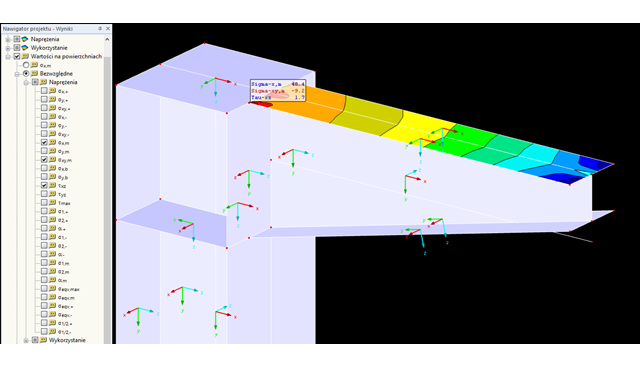
W RF-STEEL Surfaces można wyświetlić naprężenia istotne dla obliczeń spoin, na przykład zgodnie z EN 1993-1-8, rys. 4.5. Podczas analizy składowych naprężeń należy uwzględnić lokalny układ osi xyz powierzchni.