Program RFEM 6 do analizy statyczno-wytrzymałościowej jest podstawą systemu modułowego. Program główny RFEM 6 służy do definiowania konstrukcji, materiałów i obciążeń płaskich i przestrzennych układów konstrukcyjnych składających się z płyt, ścian, powłok i prętów. Program umożliwia również tworzenie konstrukcji mieszanych oraz modelowanie elementów bryłowych i kontaktowych.
RSTAB 9 to wydajne oprogramowanie do obliczeń konstrukcji szkieletowych 3D, odzwierciedlające aktualny stan wiedzy i pomagające inżynierom sprostać wymaganiom współczesnej inżynierii lądowej.
Często zbyt długo zajmujesz się obliczaniem przekrojów? Oprogramowanie firmy Dlubal i program samodzielny RSECTION ułatwiają pracę, określając i przeprowadzając analizę naprężeń dla różnych przekrojów.
Czy zawsze wiesz, skąd wieje wiatr? Oczywiście od strony innowacji! RWIND 3 to program, który wykorzystuje cyfrowy tunel aerodynamiczny do numerycznej symulacji przepływu wiatru. Program symuluje przepływ wokół dowolnej geometrii budynku i określa obciążenia wiatrem na powierzchnie.
Szukasz narzędzia do przeglądu stref obciążenia śniegiem, wiatrem i trzęsieniem ziemi? Dobrze trafiłeś! Skorzystaj z narzędzia do geolokalizacji do szybkiego i skutecznego definiowania obciążenia śniegiem, prędkości wiatru, obciążenia trzęsieniem ziemi, zgodnie z Eurokodem i innymi międzynarodowymi normami.
Chcesz wypróbować możliwości programów Dlubal Software? To Twoja szansa! Dzięki 90-dniowej pełnej wersji, możesz w pełni przetestować wszystkie nasze programy.
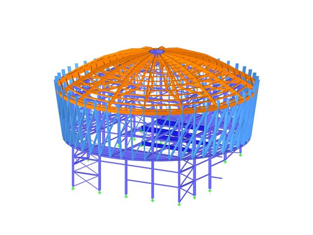
Zarówno RFEM, jak i RSTAB idealnie nadają się do modelowania i analizy statyczno-wytrzymałościowej elektrowni i konstrukcji przenośników. Je nach Aufgabenstellung können Sie Add-Ons nutzen, die auf die unterschiedlichen Disziplinen wie Massiv- oder Stahlbau abgestimmt sind.
Basisprogramme RFEM oder RSTAB
Mit den Basisprogrammen RFEM oder RSTAB wird das Modell mit seinen Eigenschaften und den Einwirkungen definiert. Dabei bietet RFEM die umfangreicheren Möglichkeiten, da mit der Finite-Elemente-Analyse auch flächige Bauteile modelliert und bemessen werden können.
Add-Ons für Kraftwerks- und Förderanlagen
Verschiedene Add-Ons ergänzen die Funktionalität der Basisprogramme. Mit den Bemessungs-Add-Ons Stahlbemessung und Betonbemessung können Sie die Tragfähigkeits-, Stabilitäts-, und Gebrauchstauglichkeitsnachweise nach verschiedenen Normen führen.
Mit dem Analyse-Add-On Wölbkrafttorsion (7 Freiheitsgrade) sind auch Biegedrillknicknachweise mit bis zu sieben Freiheitsgraden möglich. Das Add-On Spannungs-Dehnungs-Berechnung wiederum bietet die Möglichkeit für allgemeine Spannungsnachweise, bei denen die vorhandenen Spannungen mit den Grenzspannungen verglichen werden. Für plastische Untersuchungen ist das Add-On Nichtlineares Materialverhalten zu empfehlen.
Obliczenia dynamiczne
Falls Erdbebenberechnungen oder Schwingungsuntersuchungen notwendig sind, stehen mit den Add-Ons für Dynamische Analysen geeignete Werkzeuge zur Verfügung, um Eigenfrequenzen und -formen zu ermitteln oder äußere Erregungen zu untersuchen.
Bei Fragen zu den Dlubal-Lösungen für Kraftwerks- und Förderanlagen steht Ihnen unser Vertriebsteam gerne Rede und Antwort.
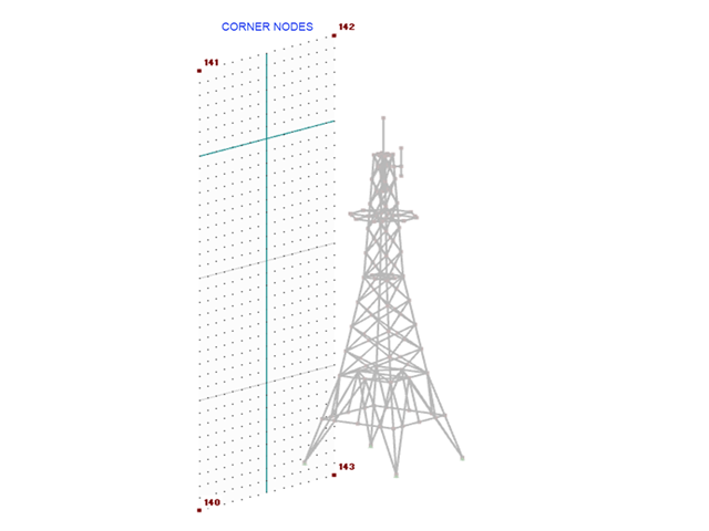
1. Zdefiniuj płaszczyznę, która zostanie użyta do przyłożenia obciążenia wiatrem. Można to zrobić, tworząc 4 węzły narożne wokół konstrukcji (rysunek 01).
Drugi Wybrać Narzędzia → Generować obciążenia → Z obciążeń powierzchniowych na prętach przy użyciu płaszczyzn. Zdefiniuj kierunek, wielkość i wybierz opcję Pusty, Tylko na prętach (zdjęcie 02). Wybierz węzły narożne, które zostały wcześniej utworzone.
3. Wybierz opcję Ustawienia dla generowania obciążenia , aby dostosować typ tolerancji. Wybierz opcję Bezwzględna za pomocą odległości i wprowadź wartość, która będzie uwzględniać całą szerokość/długość konstrukcji (rys. 03). Kliknij dwukrotnie OK , aby wyjść.
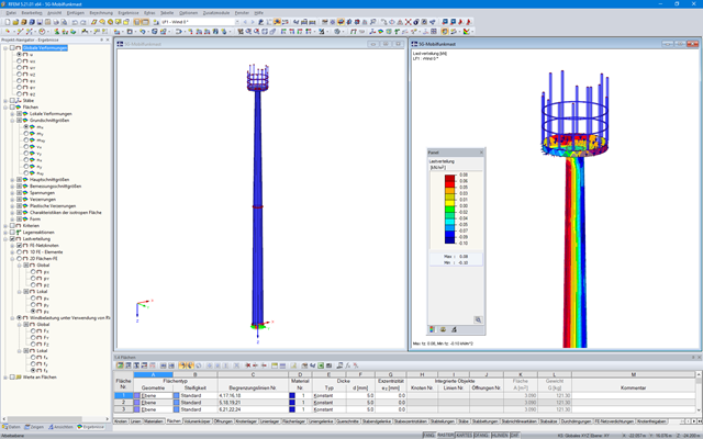
4. W tym celu należy kliknąć obciążenie powierzchniowe prawym przyciskiem myszy i wybrać opcję Wyświetlić osobno (rysunek 04). Obciążenie powierzchniowe jest teraz wyświetlane jako obciążenia prętowe (rys. 05).
Uwaga: Zastosowane obciążenie opiera się na orientacji pręta.
Zgodnie z DIN EN 1993-1:2010-12 [1] , Załącznik BB.1.1, długość wyboczeniowa może być przyjęta w indywidualnym stężeniach pod pewnymi warunkami. Oznacza to, że w tym przypadku można zastosować poszczególne pręty, a nie zbiór prętów ze współczynnikami długości efektywnej określonymi w normie.
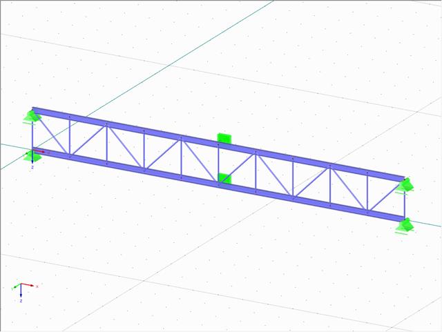
Ponieważ podejście to uwzględnia tylko zniszczenie lokalne, konieczne jest przeanalizowanie zniszczenia globalnego całej konstrukcji. W przypadku tego obliczenia zbiór prętów musi posiadać odpowiednią imperfekcję. W zależności od modelu (na przykład wieża) można, po spełnieniu określonych warunków, przeprowadzić obliczenia na pojedynczych prętach lub przeanalizować zbiór prętów pod kątem uszkodzenia od płaszczyzny (kratownica), jak w załączonym przykładzie.
Programy główne RFEM 5 lub RSTAB 8
Moduły dodatkowe
Analiza wiatru w cyfrowym tunelu aerodynamicznym