142 Wyniki
Wyświetl wyniki:
Sortuj według:

Podczas definiowania etapu budowy i obciążenia można wyświetlić zależności graficznie za pomocą schematu blokowego.

W rozszerzeniu Połączenia stalowe można używać nie tylko zwykłych typów prętów 'Belka', 'Kratownica' itd., ale także typu pręta 'Belka wynikowa' oraz przekroje z elementów powierzchniowych. Należy wybrać odpowiedni przekrój dla belki wynikowej, a następnie zdefiniować otwory prętowe w modelu powierzchniowym za pomocą edytora prętów.

Komponent 'Kontakt powierzchniowy' w rozszerzeniu Połączenia stalowe umożliwia uwzględnienie kontaktu ciśnieniowego między dwiema równoległymi płytami/płytami prętowymi. W takim przypadku można opcjonalnie uwzględnić tarcie między powierzchniami

Tabela wyników modelu budynku 'Wyniki według kondygnacji' przedstawia środek ciężkości przypadków obciążeń i kombinacji obciążeń. Oprócz obciążenia stałego uwzględniane są również obciążenia pionowe odpowiednich przypadków obciążeń i kombinacji obciążeń.
W celu wyświetlenia środka ciężkości z uwzględnieniem wybranego obciążenia można również użyć okna dialogowego 'Środek ciężkości oraz Informacje o wybranych obiektach.

W Centrum Dlubal dostępna jest obszerna biblioteka połączeń dla rozszerzenia Połączenia stalowe.
Dostęp do tej biblioteki można uzyskać bezpośrednio z rozszerzenia i przydzielić wstępnie zdefiniowane połączenia do odpowiednich węzłów. Połączenia zdefiniowane przez użytkownika można również zapisywać w bibliotece w Centrum Dlubal.

W rozszerzeniu Model budynku można zdefiniować właściwości ścian usztywniających i belek-ścian dla odpowiednich rozszerzeń.

W rozszerzeniu Połączenia stalowe można teraz układać płyty w różne kształty geometryczne. Oprócz „Prostokąta” i „Okręgu” dostępny jest nowy kształt „Wielokąt”. Forma wielokąta jest określana przez zdefiniowaną współrzędną punktu.

W rozszerzeniu Połączenie stalowe można rozmieszczać obiekty w odniesieniu do innych obiektów.

Do modelowania kondygnacji, w przypadku płyt można wykorzystać opcję "Tarcza podatna".
Zasadniczo ta opcja modelowania wybiera to samo podejście, co w przypadku modelowania kondygnacji typu "Sztywna przepona". W przeciwieństwie do sztywnej przepony, sprzężenie węzłowe nie jest przeprowadzane od środka ciężkości do każdego węzła ES. W ten sposób możliwe jest uwzględnienie elastyczności płyty.

Komponent "Stub" jest dostępny w rozszerzeniu Połączenia stalowe. Umożliwia ona wydłużenie pręta za pomocą połączenia płatwi z innym prętem (krótkiem) i połączenie go z komponentem odniesienia.

- 002842
- Ogólne informacje
- Analiza naprężeniowo-odkształceniowa RFEM 6
- Analiza naprężeniowo-odkształceniowa RSTAB 9
W rozszerzeniu Analiza naprężeniowo-odkształceniowa można użyć opcji, aby określić zależne od znaku naprężenia graniczne za pomocą składowej naprężenia.

W rozszerzeniu Połączenia stalowe można zdefiniować kilka żeber jednocześnie na jednym pręcie lub płycie. Układ może być zdefiniowany według układu ortogonalnego lub biegunowego.

- 002829
- Ogólne informacje
- Analiza naprężeniowo-odkształceniowa RFEM 6
- Analiza naprężeniowo-odkształceniowa RSTAB 9
W rozszerzeniu Analiza naprężeniowo-odkształceniowa można zdefiniować cykl naprężeń granicznych zależny od elementu i uwzględnić go w obliczeniach.

Podczas generowania ścian usztywniających i belek-ścian można przydzielać nie tylko powierzchnie i komórki, ale także pręty.

W konfiguracji granicznej dla wymiarowania połączenia stalowego istnieje możliwość modyfikacji granicznego odkształcenia plastycznego dla spoin.

Komponent "Płyta podstawy" umożliwia wymiarowanie połączeń z płytą podstawy za pomocą kotew zabetonowanych. Analizie poddawane są płyty, spoiny, zakotwienia oraz interakcja stal - beton.

W obliczeniach modelu budynku można pominąć otwory o określonej powierzchni. Funkcję tę można aktywować w ustawieniach globalnych kondygnacji budynku. Pojawi się komunikat ostrzegający, że otwory zostały pominięte.

W rozszerzeniu Analiza etapów budowy (CSA) można używać przekrojów złożonych, dzięki zastosowaniu przekrojów etapowanych. Ten typ przekroju umożliwia aktywację lub dezaktywację poszczególnych części przekroju typu "Parametryczny - Masywny II" na poszczególnych etapach budowy.

Wynik obliczeń sejsmicznych jest podzielony na dwie sekcje: wymagania dotyczące prętów i połączeń.
"Wymagania sejsmiczne" zawierają Wymaganą wytrzymałość na zginanie i Wymaganą wytrzymałość na ścinanie połączenia belka-słup dla ram sprężystych. Są one wyszczególnione w zakładce 'Połączenia ram momentowych według prętów'. W przypadku ram stężonych w zakładce 'Połączenie stężone według pręta' podawana jest Wymagana wytrzymałość połączenia na rozciąganie oraz Wymagana wytrzymałość połączenia na ściskanie stężeń.
Przeprowadzone kontrole obliczeń są przedstawiane w tabelach. W szczegółach kontroli obliczeń w przejrzysty sposób przedstawione są wzory i odniesienia do normy.
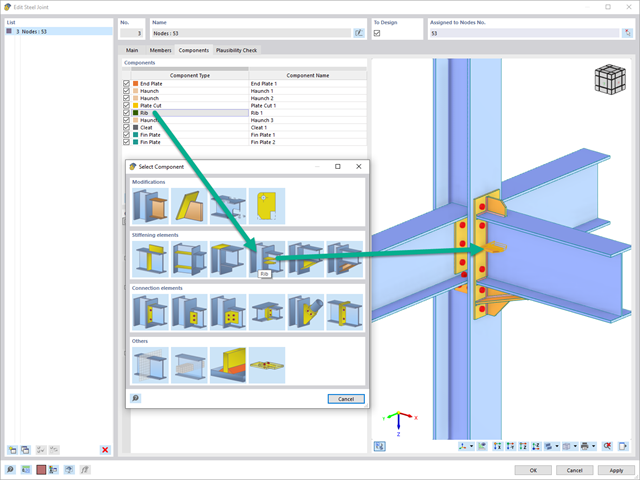
Za pomocą elementu "Żebro" można zdefiniować dowolną liczbę żeber podłużnych na blasze pręta. Wskazując obiekt odniesienia, można automatycznie określić na nim spoiny.
Komponent typu „żebro” może być również umieszczony na okrągłych profilach zamkniętych. Dafür wird zusätzlich die Vorgabe der Winkel zwischen den Rippen benötigt.

Model budynku jest obliczany w dwóch etapach:
- Globale 3D-Berechnung des Gesamtmodells, in welchem die Decken als starre Ebene (Diaphragma) oder als Biegeplatte modelliert werden
- Lokale 2D-Berechnung der einzelnen Geschossdecken
Die Ergebnisse der Stützen und Wände aus der 3D-Berechnung und die Ergebnisse der Decken aus der 2D-Berechnung werden nach der Berechnung in einem einzigen Modell zusammengefasst. Dadurch muss zwischen dem 3D-Modell und der einzelnen 2D-Modellen der Decken nicht gewechselt werden. Der Anwender arbeitet nur mit einem Model, spart wertvolle Zeit und vermeidet eventuelle Fehler beim händischen Datenaustausch zwischen dem 3D-Modell und der einzelnen 2D-Decken-Modelle.
Die vertikalen Flächen im Modell können vom Nutzer in Schubwände (Shear Walls) und Öffnungsstürze (Sprandels) geteilt werden. Aus diesen Wandobjekten erzeugt das Programm automatisch interne Ergebnisstäbe, so dass diese dann nach der gewünschten Norm im Add-On Betonbemessung für RFEM 6 als Stäbe bemessen werden können.

Ściany usztywniające i belki-ściany z modelu budynku są dostępne jako niezależne obiekty w rozszerzeniach. W ten sposób możliwe jest szybsze filtrowanie obiektów w wynikach oraz tworzenie lepszej dokumentacji w raporcie.

Teraz za pomocą kilku kliknięć można wstawiać blachy czołowe w połączeniach stalowych. Dane można wprowadzać za pomocą znanych typów definicji 'Offset' lub 'Wymiary i położenie'. Wprowadzając pręt odniesienia i płaszczyznę cięcia, można również pominąć część Przekrój pręta.
Za pomocą tego komponentu można łatwo modelować na przykład blachy czołowe na końcach słupa.

Rozszerzenie Analiza modalna umożliwia automatyczne zwiększanie poszukiwanych wartości własnych do momentu osiągnięcia zdefiniowanego współczynnika efektywnej masy modalnej. Uwzględniane są wszystkie kierunki translacyjne, które zostały aktywowane jako masy do analizy modalnej.
W ten sposób można łatwo obliczyć wymagane 90% efektywnej masy modalnej dla metody spektrum odpowiedzi.

Za pomocą generatora kondygnacji w rozszerzeniu Model budynku można automatycznie tworzyć kondygnacje budynku w zależności od topologii modelu.

- 002733
- Ogólne informacje
- Projektowanie konstrukcji stalowych RFEM 6
- Projektowanie konstrukcji stalowych RSTAB 9
Rozszerzenie Projektowanie konstrukcji stalowych umożliwia przeprowadzanie obliczeń sejsmicznych prętów stalowych zgodnie z AISC 341-16.
W tym celu dostępnych jest pięć typów systemów SFRS (Seismic Force-Resisting Systems).

W przypadku analizy spektrum odpowiedzi modeli budynków można wyświetlić współczynniki wrażliwości dla kierunków poziomych według kondygnacji.
Dzięki tym kluczowym wartościom można zinterpretować wrażliwość na efekty stateczności.

Za pomocą komponentu "Cięcie płyty" można ciąć blachy (np. blachy węzłowe, blachy środnika itp.). Dostępne są różne metody cięcia:
- Płaszczyzna: Cięcie jest wykonywane na powierzchni najbliższej płycie odniesienia.
- Powierzchnia: Wycinane są tylko przecinające się części płyt.
- Bryła ograniczająca: Najbardziej zewnętrzny wymiar, szerokość i wysokość, jest wycinany jako prostokąt.
- Otoczka wypukła: Zewnętrzna otoczka przekroju służy do przycinania płyty. Jeżeli w węzłach narożnych przekroju występują zaokrąglenia, cięcie jest do nich dostosowywane.
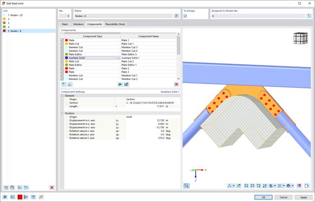
W rozszerzeniu Połączenie stalowe można użyć elementu "Bryła pomocnicza", aby dokładnie ciąć płyty i inne elementy konstrukcyjne. W ramach tego elementu, rolę obiektu pomocniczego mogą pełnić kształty takie jak sześcian, walec lub dowolny przekrój.
Przejdź do filmu
W rozszerzeniu Połączenia stalowe można łączyć profile zamknięte o przekroju okrągłym za pomocą spoin.
Profile okrągłe można łączyć ze sobą lub z płaskimi elementami konstrukcyjnymi. Spoiną można również łączyć pachwiny przekrojów znormalizowanych i cienkościennych.
Przejdź do filmu