138 Wyniki
Wyświetl wyniki:
Sortuj według:

- 002111
- Ogólne informacje
- Analiza naprężeniowo-odkształceniowa RFEM 6
- Analiza naprężeniowo-odkształceniowa RSTAB 9
- Ogólna analiza naprężeniowa
- Automatyczny import sił wewnętrznych z programu RFEM/RSTAB
- Graficzne i numeryczne przedstawianie naprężeń, odkształceń, luzu i stopni wykorzystania w pełni zintegrowane z RFEM/RSTAB
- Zdefiniowana przez użytkownika specyfikacja naprężenia granicznego
- Podsumowanie podobnych elementów konstrukcyjnych do obliczeń
- Szeroki zakres opcji umożliwiających dostosowywania sposobu wyświetlania wyników
- Przejrzyste tabele wyników dla szybkiego ich przeglądania po zakończeniu obliczeń
- Łatwa możliwość identyfikacji wyników dzięki w pełni udokumentowanej metodzie obliczeniowej wraz ze wszystkimi wzorami
- Wysoka wydajność pracy dzięki minimalnej ilości danych wejściowych
- Elastyczność dzięki szczegółowym opcjom ustawień dla podstawy i zakresu obliczeń
- Wyświetlanie szarej strefy dla nieistotnych zakresów wartości: Funkcja produktu "Analiza naprężeniowo-odkształceniowa z wyświetlaniem w szarej strefie"

- 002112
- Ogólne informacje
- Analiza naprężeniowo-odkształceniowa RFEM 6
- Analiza naprężeniowo-odkształceniowa RSTAB 9
- Optymalizacja przekroju
- Transfer zoptymalizowanych przekrojów do RFEM/RSTAB
- Wymiarowanie dowolnego przekroju cienkościennego z RSECTION
- Odwzorowanie wykresu naprężeń na przekroju
- Wyznaczanie naprężeń normalnych, ścinających i równoważnych
- Wyświetlanie składowych naprężeń dla poszczególnych typów sił wewnętrznych pręta
- Szczegółowe przedstawienie naprężeń we wszystkich punktach naprężeniowych
- Wyznaczanie największego Δσ dla każdego punktu naprężenia (na przykład do obliczeń zmęczenia)
- Wyświetlanie w kolorze naprężeń i stopni wykorzystania w celu szybkiego przeglądu stref krytycznych lub przewymiarowanych
- Wyświetlanie wykazów materiałów

- Wyznaczanie naprężeń głównych i podstawowych, naprężeń membranowych i stycznych oraz naprężeń zastępczych i zastępczych naprężeń membranowych
- Analiza naprężeń dla elementów konstrukcyjnych o dowolnym kształcie
- Obliczanie naprężeń zastępczych według różnych metod:
- Hipoteza energii odkształcenia (von Mises)
- Schubspannungshypothese (Tresca)
- Normalspannungshypothese (Rankine)
- Hauptdehnungshypothese (Bach)
- Możliwość optymalizacji grubości powierzchni i transferu danych do programu RFEM
- Ausgabe der Dehnungen
- Szczegółowe wyniki dla różnych składników naprężeń i stopni wykorzystania w tabelach i w grafice
- Filtermöglichkeit für Volumenkörper, Flächen, Linien und Knoten in Tabellen
- Querschubspannungen nach Mindlin, Kirchhoff oder freier Eingabe
- Spannungsauswertung für Schweißnähte an Verbindungslinien zwischen Flächen: Przejdź do funkcji produktu "Spoina liniowa"

- 002115
- Wyniki
- Analiza naprężeniowo-odkształceniowa RFEM 6
- Analiza naprężeniowo-odkształceniowa RSTAB 9
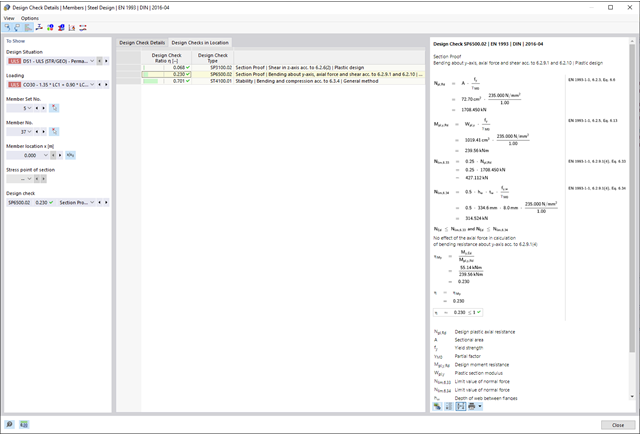
Po zakończeniu obliczeń wyniki są uporządkowane w sposób przejrzysty. W ten sposób program wyświetla maksymalne naprężenia i stopnie naprężeń posortowane według przekroju, pręta/powierzchni, bryły, zbioru prętów, położenia x itd. Oprócz wartości wyników w formie tabelarycznej rozszerzenie wyświetla również odpowiednią grafikę przekroju z punktami naprężeniowymi, wykresem naprężeń i wartościami. Stopień wykorzystania można odnieść do dowolnego rodzaju naprężenia. Aktualnie wybrana lokalizacja na elemencie zostanie wyróżniona na modelu analitycznym w programie RFEM/RSTAB.
Oprócz oceny tabelarycznej program oferuje jeszcze więcej. Naprężenia i stopnie wykorzystania można również sprawdzić graficznie na modelu w programie RFEM/RSTAB. Istnieje możliwość indywidualnego dostosowania kolorów i wartości.
Wyświetlanie wykresów wyników dla pręta lub zbioru prętów umożliwia dokładną ocenę. Dla każdego miejsca obliczeniowego można otworzyć odpowiednie okno dialogowe, w którym można sprawdzić odpowiednie do obliczeń właściwości przekroju i składowe naprężeń w dowolnym punkcie naprężeniowym. Na koniec istnieje możliwość wydrukowania odpowiedniej grafiki wraz ze wszystkimi szczegółami obliczeń.

- 002129
- Ogólne informacje
- Projektowanie konstrukcji stalowych RFEM 6
- Projektowanie konstrukcji stalowych RSTAB 9
- Szeroki wybór dostępnych przekrojów, takich jak dwuteowniki walcowane; ceowniki; teowniki; kątowniki; profile zamknięte prostokątne i okrągłe; pręty okrągłe; przekroje symetryczne i niesymetryczne, parametryczne przekroje dwuteowe, teowe, kątowniki; przekroje złożone (przydatność do obliczeń zależy od wybranej normy)
- Wymiarowanie ogólnych przekrojów RSECTION (w zależności od formatów obliczeniowych dostępnych w odpowiedniej normie); na przykład obliczanie naprężeń zastępczych
- Wymiarowanie prętów o zbieżnym przekroju (metoda zależna od normy)
- Możliwe jest dostosowanie istotnych współczynników obliczeniowych i parametrów normowych
- Elastyczność dzięki szczegółowym opcjom ustawień dla podstawy i zakresu obliczeń
- Szybkie i przejrzyste wyświetlanie wyników dla globalnej oceny ich rozkładu na konstrukcji po zakończeniu obliczeń
- Szczegółowe wyniki obliczeń i niezbędne wzory (jasna i łatwa do zweryfikowania ścieżka wyników)
- Przejrzyste zestawienie wyników w formie numerycznej w stosownych oknach oraz możliwość ich graficznego przedstawienia na konstrukcji
- Integracja wyników z protokołem wydruku programu RFEM/RSTAB
- 002130
- Ogólne informacje
- Projektowanie konstrukcji stalowych RFEM 6
- Projektowanie konstrukcji stalowych RSTAB 9
- Wymiarowanie elementów rozciąganych, ściskanych, zginanych, ścinanych, skręcanych i poddanych połączonemu działaniu tych sił wewnętrznych
- Obliczanie rozciągania z uwzględnieniem zredukowanej powierzchni przekroju (np. osłabienie z uwagi na otwory)
- Automatyczna klasyfikacja przekrojów w celu sprawdzenia wyboczenia lokalnego
- Siły wewnętrzne z obliczeń ze skręcaniem skrępowanym (7 stopni swobody) są uwzględniane w kontroli naprężeń zastępczych (obecnie nie dla norm projektowych AISC 360-16 i GB 50017).
- Wymiarowanie przekrojów klasy 4 o właściwościach efektywnych zgodnie z EN 1993-1-5 oraz przekrojów formowanych na zimno zgodnie z EN 1993-1-3, AISI S100 lub CSA S136 (licencje dla RSECTION i "Przekroje efektywne" " są wymagane dla przekrojów RSECTION)
- Sprawdzenie wyboczenia przy ścinaniu zgodnie z EN 1993-1-5 z uwzględnieniem usztywnień poprzecznych
- Wymiarowanie elementów ze stali nierdzewnej zgodnie z EN 1993‑1-4
- 002131
- Obliczenia
- Projektowanie konstrukcji stalowych RFEM 6
- Projektowanie konstrukcji stalowych RSTAB 9
- Analiza stateczności dla wyboczenia giętnego, wyboczenia skrętnego i wyboczenia giętno-skrętnego przy ściskaniu
- Import długości efektywnych z obliczeń przy użyciu rozszerzenia Stateczność konstrukcji
- Graficzne wprowadzanie i kontrola zdefiniowanych podpór węzłowych oraz długości efektywnych w celu analizy stateczności
- Analiza zwichrzenia elementów poddanych obciążeniu momentem
- W zależności od normy istnieje wybór między wprowadzaniem wartości Mcr przez użytkownika, metodą analityczną z normy lub wykorzystaniem wewnętrznego solwera wartości własnych
- Uwzględnienie panelu usztywniającego i ograniczenia obrotu podczas korzystania z solwera wartości własnych
- Graficzne przedstawienie postaci własnej w przypadku zastosowania solwera wartości własnych
- Analiza stateczności elementów konstrukcyjnych ze ściskaniem i naprężeniem zginającym, w zależności od normy obliczeniowej
- Przejrzyste obliczenia wszystkich niezbędnych współczynników, takich jak współczynniki uwzględniające rozkładu momentów lub współczynniki interakcji
- Alternatywne uwzględnienie wszystkich wpływów dla analizy stateczności podczas określania sił wewnętrznych w programie RFEM/RSTAB (analiza drugiego rzędu, imperfekcje, redukcja sztywności, ewentualnie w połączeniu z rozszerzeniem Skręcanie skrępowane (7 stopni swobody))

- 002132
- Wyniki
- Projektowanie konstrukcji stalowych RFEM 6
- Projektowanie konstrukcji stalowych RSTAB 9
Układ konstrukcyjny należy wprowadzić i obliczyć siły wewnętrzne w programach RFEM i RSTAB. Użytkownik ma pełny dostęp do obszernych bibliotek materiałów i przekrojów. Masz pytania dotyczące programu? W programie RSECTION można również tworzyć przekroje ogólne.
Projektowanie konstrukcji stalowych jest w pełni zintegrowane z programami głównymi. Uwzględniają one automatycznie konstrukcję i dostępne wyniki obliczeń. Do wymiarowania konstrukcji aluminiowych można przydzielić dodatkowe dane, takie jak długości efektywne, redukcje przekroju lub parametry obliczeniowe. W wielu miejscach programu można łatwo wybrać elementy graficznie za pomocą funkcji [Wybierz].

- 002140
- Ogólne informacje
- Projektowanie konstrukcji aluminiowych RFEM 6
- Projektowanie konstrukcji aluminiowych RSTAB 9
- Szeroki wybór dostępnych przekrojów, takich jak dwuteowniki walcowane; ceowniki; teowniki; kątowniki; profile zamknięte prostokątne i okrągłe; pręty okrągłe; przekroje symetryczne i niesymetryczne, parametryczne przekroje dwuteowe, teowe, kątowniki; przekroje złożone (przydatność do obliczeń zależy od wybranej normy)
- Wymiarowanie ogólnych przekrojów RSECTION (w zależności od formatów obliczeniowych dostępnych w odpowiedniej normie); na przykład obliczanie naprężeń zastępczych
- Wymiarowanie prętów o zbieżnym przekroju (metoda zależna od normy)
- Możliwe jest dostosowanie istotnych współczynników obliczeniowych i parametrów normowych
- Elastyczność dzięki szczegółowym opcjom ustawień dla podstawy i zakresu obliczeń
- Szybkie i przejrzyste wyświetlanie wyników dla globalnej oceny ich rozkładu na konstrukcji po zakończeniu obliczeń
- Szczegółowe wyniki obliczeń i niezbędne wzory (jasna i łatwa do zweryfikowania ścieżka wyników)
- Przejrzyste zestawienie wyników w formie numerycznej w stosownych oknach oraz możliwość ich graficznego przedstawienia na konstrukcji
- Integracja wyników z protokołem wydruku programu RFEM/RSTAB

- 002141
- Ogólne informacje
- Projektowanie konstrukcji aluminiowych RFEM 6
- Projektowanie konstrukcji aluminiowych RSTAB 9
- Wymiarowanie elementów rozciąganych, ściskanych, zginanych, ścinanych, skręcanych i poddanych połączonemu działaniu tych sił wewnętrznych
- Obliczanie rozciągania z uwzględnieniem zredukowanej powierzchni przekroju (np. osłabienie z uwagi na otwory)
- Automatyczna klasyfikacja przekrojów w celu sprawdzenia wyboczenia lokalnego
- Siły wewnętrzne z obliczeń ze skręcaniem skrępowanym (7 stopni swobody) są uwzględniane w kontroli naprężeń zastępczych (obecnie nie dla normy ADM 2020)
- Wymiarowanie przekrojów klasy 4 o właściwościach przekroju efektywnego zgodnie z EN 1999-1-1 (dla przekrojów RSECTION wymagane są licencje dla przekrojów RSECTION i "Przekroje efektywne")
- Sprawdzenie wyboczenia przy ścinaniu z uwzględnieniem usztywnień poprzecznych

- 002142
- Wyniki
- Projektowanie konstrukcji aluminiowych RFEM 6
- Projektowanie konstrukcji aluminiowych RSTAB 9
- Analiza stateczności dla wyboczenia giętnego, wyboczenia skrętnego i wyboczenia giętno-skrętnego przy ściskaniu
- Analiza zwichrzenia elementów poddanych obciążeniu momentem
- Import długości efektywnych z obliczeń przy użyciu rozszerzenia Stateczność konstrukcji
- Graficzne wprowadzanie i kontrola zdefiniowanych podpór węzłowych oraz długości efektywnych w celu analizy stateczności
- W zależności od normy istnieje wybór między wprowadzaniem wartości Mcr przez użytkownika, metodą analityczną z normy lub wykorzystaniem wewnętrznego solwera wartości własnych
- Uwzględnienie panelu usztywniającego i ograniczenia obrotu podczas korzystania z solwera wartości własnych
- Graficzne przedstawienie postaci własnej w przypadku zastosowania solwera wartości własnych
- Analiza stateczności elementów konstrukcyjnych ze ściskaniem i naprężeniem zginającym, w zależności od normy obliczeniowej
- Przejrzyste obliczanie wszystkich niezbędnych współczynników, takich jak współczynniki interakcji
- Alternatywne uwzględnienie wszystkich wpływów dla analizy stateczności podczas określania sił wewnętrznych w programie RFEM/RSTAB (analiza drugiego rzędu, imperfekcje, redukcja sztywności, ewentualnie w połączeniu z rozszerzeniem Skręcanie skrępowane (7 stopni swobody))

- 002304
- Ogólne informacje
- Projektowanie konstrukcji stalowych RFEM 6
- Projektowanie konstrukcji stalowych RSTAB 9
- W przypadku obliczeń zgodnie z Eurokodem 3 parametry załączników krajowych (NA) są zintegrowane dla następujących krajów:
-
 DIN EN 1993-1-1/NA:2016-04 (Niemcy)
 -
 ÖNORM EN 1993-1-1/NA:2015-12 (Austria)
 -
 SN EN 1993-1-1/NA:2016-07 (Szwajcaria)
 -
 BDS EN 1993-1-1/NA:2015-10 (Bułgaria)
 -
 BS EN 1993-1-1/NA:2016-07 (Wielka Brytania)
 -
 CEN EN 1993-1-1/2015-06 (Unia Europejska)
 -
 CYS EN 1993-1-1/NA:2015-07 (Cypr)
 -
 CZE EN 1993-1-1/NA:2016-06 (Republika Czeska)
 -
 DS EN 1993-1-1/NA:2015-07 (Dania)
 -
 ELOT EN 1993-1-1/NA:2017-01 (Grecja)
 -
 EVS EN 1993-1-1/NA:2015-08 (Estonia)
 -
 HRN EN 1993-1-1/NA:2016-03 (Chorwacja)
 -
 I S. EN 1993-1-1/NA:2016-03 (Irlandia)
 -
 ILNAS EN 1993-1-1/NA:2015-06 (Luksemburg)
 -
 IST EN 1993-1-1/NA:2015-11 (Islandia)
 -
 LST EN 1993-1-1/NA:2017-01 (Litwa)
 -
 LVS EN 1993-1-1/NA:2015-10 (Łotwa)
 -
 MS EN 1993-1-1/NA:2010-01 (Malezja)
 -
 MSZ EN 1993-1-1/NA:2015-11 (Węgry)
 -
 NBN EN 1993-1-1/NA:2015-07 (Belgia)
 -
 NEN EN 1993-1-1/NA:2016-12 (Holandia)
 -
 NF EN 1993-1-1/NA:2016-02 (Francja)
 -
 NP EN 1993-1-1/NA:2009-03 (Portugalia)
 -
 NS EN 1993-1-1/NA:2015-09 (Norwegia)
 -
 PN EN 1993-1-1/NA:2015-08 (Polska)
 -
 SFS EN 1993-1-1/NA:2015-08 (Finlandia)
 -
 SIST EN 1993-1-1/NA:2016-09 (Słowenia)
 -
 SR EN 1993-1-1/NA:2016-04 (Rumunia)
 -
 SS EN 1993-1-1/NA:2019-05 (Singapur)
 -
 SS EN 1993-1-1/NA:2015-06 (Szwecja)
 -
 STN EN 1993-1-1/NA:2015-10 (Słowacja)
 -
 TKP EN 1993-1-1/NA:2015-04 (Białoruś)
 -
 UNE EN 1993-1-1/NA:2016-02 (Hiszpania)
 -
 UNI EN 1993-1-1/NA:2015-08 (Włochy)
-
- W obliczeniach zgodnie z amerykańską normą AISC 360 uwzględniono następujące metody analizy:
-
 Obliczenia współczynnika obciążenia i odporności (LRFD)
 -
Projektowanie dopuszczalnych naprężeń (ASD)
-

Parametry załączników krajowych (NA) do Eurokodu 3 z następujących krajów są zintegrowane:
-
DIN EN 1993-1-1/NA:2016-04 (Niemcy)
-
ÖNORM EN 1993-1-1/NA:2015-12 (Austria)
-
SN EN 1993-1-1/NA:2016-07 (Szwajcaria)
-
BDS EN 1993-1-1/NA:2015-10 (Bułgaria)
-
BS EN 1993-1-1/NA:2016-07 (Wielka Brytania)
-
CEN EN 1993-1-1/2015-06 (Unia Europejska)
-
CYS EN 1993-1-1/NA:2015-07 (Cypr)
-
CSN EN 1993-1-1/NA:2016-06 (Republika Czeska)
-
DS EN 1993-1-1/NA:2015-07 (Dania)
-
ELOT EN 1993-1-1/NA:2017-01 (Grecja)
-
EVS EN 1993-1-1/NA:2015-08 (Estonia)
-
HRN EN 1993-1-1/NA:2016-03 (Chorwacja)
-
I S. EN 1993-1-1/NA:2016-03 (Irlandia)
-
ILNAS EN 1993-1-1/NA:2015-06 (Luksemburg)
-
IST EN 1993-1-1/NA:2015-11 (Islandia)
-
LST EN 1993-1-1/NA:2017-01 (Litwa)
-
LVS EN 1993-1-1/NA:2015-10 (Łotwa)
-
MS EN 1993-1-1/NA:2010-01 (Malezja)
-
MSZ EN 1993-1-1/NA:2015-11 (Węgry)
-
NBN EN 1993-1-1/NA:2015-07 (Belgia)
-
NEN EN 1993-1-1/NA:2016-12 (Holandia)
-
NF EN 1993-1-1/NA:2016-02 (Francja)
-
NP EN 1993-1-1/NA:2009-03 (Portugalia)
-
NS EN 1993-1-1/NA:2015-09 (Norwegia)
-
PN EN 1993-1-1/NA:2015-08 (Polska)
-
SFS EN 1993-1-1/NA:2015-08 (Finlandia)
-
SIST EN 1993-1-1/NA:2016-09 (Słowenia)
-
SR EN 1993-1-1/NA:2016-04 (Rumunia)
-
SS EN 1993-1-1/NA:2019-05 (Singapur)
-
SS EN 1993-1-1/NA:2015-06 (Szwecja)
-
STN EN 1993-1-1/NA:2015-10 (Słowacja)
-
TKP EN 1993-1-1/NA:2015-04 (Białoruś)
-
UNE EN 1993-1-1/NA:2016-02 (Hiszpania)
-
UNI EN 1993-1-1/NA:2015-08 (Włochy)
- 002336
- Wyniki
- Projektowanie konstrukcji stalowych RFEM 6
- Projektowanie konstrukcji stalowych RSTAB 9
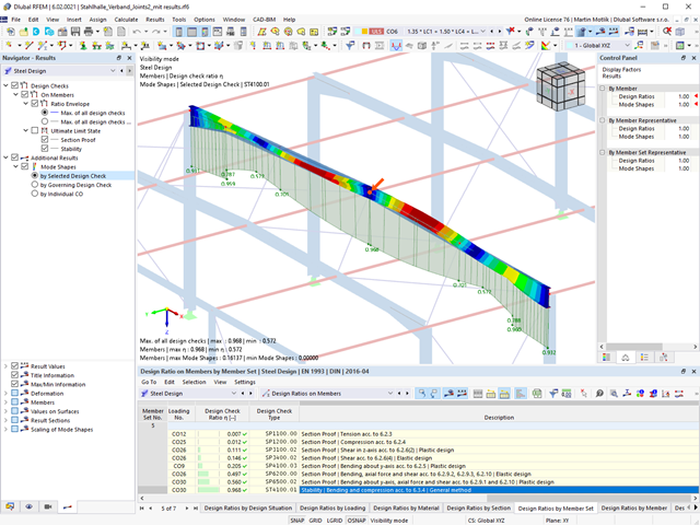
Czy projekt zakończył się sukcesem? Usiądź wygodnie i zrelaksuj się. Przeprowadzone kontrole obliczeń są wyświetlane w tabelach. Wszystkie szczegóły wyników są wyświetlane i można je łatwo śledzić dzięki przejrzyście ułożonym wzorom obliczeniowym.
Weryfikacje są przeprowadzane we wszystkich decydujących miejscach prętów. Wykres wyników dostępny jest w postaci graficznej. Ponadto, użytkownik ma dostęp do szczegółowych grafik, takich jak rozkład naprężeń w przekroju lub decydujący kształt drgań własnych, dostępnych w wynikach.
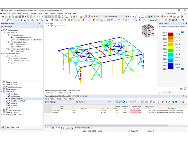
Wszystkie dane wejściowe i wyniki są częścią protokołu wydruku programu RFEM/RSTAB. Zawartość i zakres protokołu można wybrać specjalnie dla poszczególnych warunków projektowych.
_(1).png?mw=640&hash=415f7bbaf70e41679bb0106e1cf91eaa8c493ec9)
- Automatyczne generowanie modeli do analizy ES: rozszerzenie automatycznie tworzy w tle model elementów skończonych (ES) połączenia stalowego.
- Uwzględnienie wszystkich sił wewnętrznych: Obliczenia obejmują wszystkie siły wewnętrzne (N , Vy, Vz ,My, Mz, MT ) i nie są ograniczone do obciążeń płaskich.
- Automatyczne przenoszenie obciążeń: Wszystkie kombinacje obciążeń są automatycznie przenoszone do modelu analitycznego ES połączenia. Obciążenia są przenoszone bezpośrednio z programu RFEM, dzięki czemu ręczne wprowadzanie danych nie jest konieczne.
- Wydajne modelowanie: Rozszerzenie pozwala zaoszczędzić czas podczas modelowania złożonych sytuacji związanych z połączeniami. Utworzony model analityczny ES można również zapisać i wykorzystać do własnych szczegółowych analiz.
- Rozszerzalna biblioteka: Dostępna jest obszerna, rozszerzalna biblioteka zawierająca wstępnie zdefiniowane szablony połączeń stalowych.
- Szerokie zastosowanie: Rozszerzenie jest odpowiednie do tworzenia połączeń każdego typu i kształtu, jest kompatybilne z prawie wszystkimi przekrojami walcowanymi, spawanymi, złożonymi i cienkościennymi.

- Wybór węzłów w modelu RFEM, automatyczne rozpoznawanie i przydzielanie prętów połączonych z wybranym węzłem
- Dostępnych jest wiele wstępnie zdefiniowanych elementów ułatwiających wprowadzanie typowych komponentów połączeń (np. blachy czołowe, żebra usztywniające)
- Uniwersalne komponenty bazowe (płyty, spoiny, płaszczyzny pomocnicze) do odwzorowania złożonych geometrii połączeń
- Użytkownik nie musi ręcznie edytować modelu MES połączenia, podstawowe ustawienia obliczeń można zmienić w oknie konfiguracji połączenia
- Automatyczne dostosowywanie geometrii połączenia, nawet w przypadku późniejszej edycji prętów, z uwagi na parametryczną definicję położenia komponentów względem siebie
- Równolegle do wprowadzania danych program przeprowadza kontrolę poprawności, aby szybko wykryć brakujące dane wejściowe lub kolizje elementów.
- Wizualizacja geometrii połączenia, która jest aktualizowana równolegle z wprowadzaniem danych
Program wspiera Cię: Moduł określa siły w śrubach na podstawie modelu analitycznego ES i analizuje je automatycznie. Rozszerzenie przeprowadza obliczenia nośności śrub dla przypadków uszkodzeń, takich jak rozciąganie, ścinanie, docisk otworu i przebicie, zgodnie z normą i wyświetla w przejrzysty sposób wszystkie wymagane współczynniki.
Chcesz przeprowadzić wymiarowanie spoin? Spoiny są modelowane jako sprężysto-plastyczne elementy powierzchniowe, a ich naprężenia są odczytywane z modelu analitycznego ES. Kryterium plastyczności ma reprezentować zniszczenie zgodnie z AISC J2-4, J2-5 (wytrzymałość spoin) i J2-2 (wytrzymałość metalu podstawowego). Obliczenia można przeprowadzić z zastosowaniem częściowych współczynników bezpieczeństwa określonych w załączniku krajowym do normy EN 1993-1-8.
Płyty w połączeniu są wymiarowane w sposób plastyczny poprzez porównanie istniejącego odkształcenia plastycznego z dopuszczalnym odkształceniem plastycznym. Domyślne ustawienie wynosi 5% zgodnie z EN 1993-1-5, Załącznik C, ale można to zmienić według specyfikacji użytkownika, a także 5% dla AISC 360.
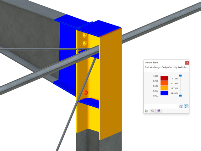
Wszystkie istotne wyniki można wyświetlić w modelu ES. W takim przypadku można filtrować wyniki osobno według odpowiednich komponentów.
Ponadto program RFEM zapewnia wszystkie kontrole obliczeń w formie tabelarycznej wraz z wyświetlaniem zastosowanych wzorów. W razie potrzeby tabele wyników można przenieść do protokołu wydruku programu RFEM.
- 002169
- Ogólne informacje
- Analiza naprężeniowo-odkształceniowa RFEM 6
- Analiza naprężeniowo-odkształceniowa RSTAB 9
W porównaniu z modułem dodatkowym RF-/STEEL (RFEM 5/RSTAB 8) do rozszerzenia Analiza naprężeniowo-odkształceniowa dla programu RFEM 6/RSTAB 9 dodano następujące nowe funkcje:
- Możliwość analizy prętów, powierzchni, brył, spoin (połączenia spawane liniowo między dwiema i trzema powierzchniami z późniejszym obliczaniem naprężeń)
- Wyświetlanie naprężeń, stopni naprężeń, zakresów naprężeń i odkształceń
- Naprężenie graniczne w zależności od przydzielonego materiału lub danych wejściowych zdefiniowanych przez użytkownika
- Indywidualne określenie wyników do obliczeń poprzez dowolnie przydzielane typów ustawień
- Szczegóły dla wyników niemodalnych z wyświetlaniem przygotowanego wzoru i dodatkowym wyświetlaniem wyników na poziomie przekroju prętów
- Możliwość wygenerowania zastosowanych wzorów do kontroli obliczeń

- 002171
- Ogólne informacje
- Projektowanie konstrukcji stalowych RFEM 6
- Projektowanie konstrukcji stalowych RSTAB 9
W porównaniu z modułem dodatkowym RF-/STEEL EC3 (RFEM 5/RSTAB 8) do rozszerzenia Wymiarowanie stali dla programu RFEM 6/RSTAB 9 dodano następujące nowe funkcje:
- Oprócz Eurokodu 3, uwzględnione zostały inne międzynarodowe normy (np. AISC 360, CSA S16, GB 50017, SP 16.13330)
- Berücksichtigung der Feuerverzinkung (DASt-Richtlinie 027) beim Brandschutznachweis nach EN 1993-1-2
- Opcja wprowadzania żeber usztywniających, które można uwzględnić w analizie wyboczenia
- Wyboczenie skrętne można również sprawdzić w przypadku przekrojów zamkniętych (np. istotne dla smukłych, wysokich prostokątnych przekrojów zamkniętych)
- Automatyczne wykrywanie prętów lub zbiorów prętów ważnych dla obliczeń (np. automatyczna dezaktywacja prętów z nieaktualnym materiałem lub prętów już zawartych w zbiorze prętów)
- Możliwość dostosowania ustawień obliczeniowych indywidualnie dla każdego pręta
- Graficzne przedstawienie wyników w przekroju brutto lub przekroju efektywnym
- Wyświetlanie odpowiednich wzorów użytych do sprawdzania warunków nośności (w tym odniesienie do zastosowanego równania z normy)