The "Surface Reinforcements" type allows you to define how to carry out the reinforcement of a surface using rebars or meshes.
Input Options
The program provides several options for entering surface reinforcements.
Shortcut Menu of Navigator
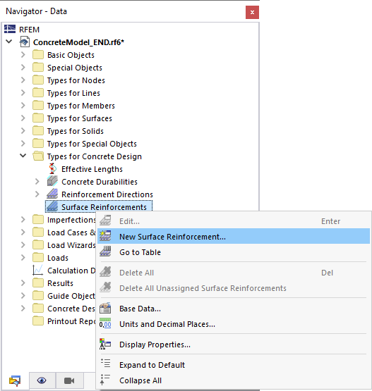
In the "Navigator - Data", right-click the Surface Reinforcements category. Then, select New Surface Reinforcement from the shortcut menu.
Table
In the table, set the Structure main category and the Types for Concrete Design subcategory. Double-click an empty row in the Surface Reinforcements worksheet.

Surface Property
You can create a new surface reinforcement directly as a property of a surface. Open the Edit Surface dialog box and switch to the Surface Reinforcement tab.

Main
In the Main tab, you can define the main specifications of a surface reinforcement.

Location Type
The location type defines the basic geometric properties of the surface reinforcement.
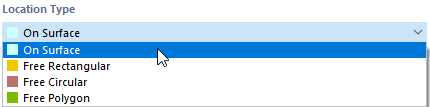
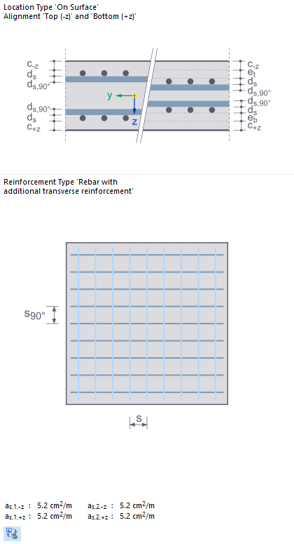
The "On Surface" location type is set by default. Thus, the reinforcement defined in the other sections will be applied over the entire surface.
For the types "Free Rectangular", "Free Circular", and "Free Polygon", you can specify such a surface reinforcement geometry that is independent of the geometry of the actual surface.
Reinforcement
Material
Assign material to the surface reinforcement. If you have already defined the suitable reinforcement steel in the model, it is available for selection in the list. Otherwise, you can use the
![]() button to create a new material and open the
New Material
dialog box, where you can access the material library. You can also directly open this library by clicking the
button to create a new material and open the
New Material
dialog box, where you can access the material library. You can also directly open this library by clicking the
![]() button. The "Reinforcing Steel" material is preset here.
button. The "Reinforcing Steel" material is preset here.
Use the
![]() button to change the material that has already been assigned. The
button to change the material that has already been assigned. The
![]() button allows you to graphically transfer the reinforcing steel from another surface.
button allows you to graphically transfer the reinforcing steel from another surface.
Reinforcement Type
The reinforcement type specifies the type of surface reinforcement.
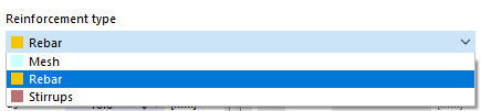
- Rebar
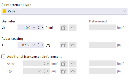
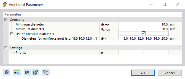
Enter the "Diameter" ds of the rebars and the "Rebar spacing"' s. These entries refer to Direction 1 of the reinforcement ("main reinforcement"). If the program should design a diameter or a distance in the design, select the Automatically option.
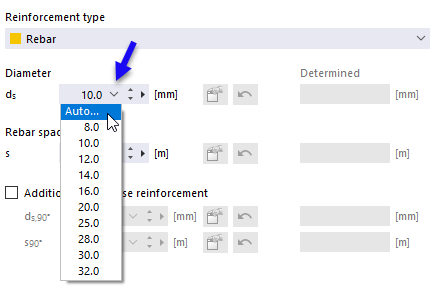
You can then specify the parameters in a separate dialog box.
If you want to additionally apply the reinforcement orthogonal to Direction 1, activate the "Additional transverse reinforcement" check box. This activates the text boxes for the reinforcement direction 2, where you can define a diameter ds,90° and a rebar spacing s90°.
- Mesh
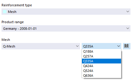
In the list, select a "product range" for support meshes that is available for certain countries. In the "Mesh" list, you can then define the mesh type and select a specific shape.
Click the
![]() button to access the extensive library of reinforcing steel meshes. You can select a product range in the "Filter" section and import the relevant mesh.
button to access the extensive library of reinforcing steel meshes. You can select a product range in the "Filter" section and import the relevant mesh.

- Stirrup
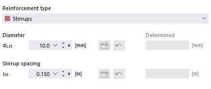
For shear reinforcement, enter the "Diameter" ds,st of the members and the "Stirrup spacing" sst.
Assignment
Use the check boxes in this dialog box section to define the surface side(s) where the longitudinal reinforcement is located. This option is not available for a stirrup reinforcement.
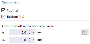
If you assign several reinforcement layers on top of each other (an additional reinforcement) to a surface, you can consider the eccentricity of the layers as an "Additional offset to concrete cover". Here, you can define the dimensions eo (top layer) and eu (bottom layer) for the additional reinforcement. In the infographic on the right, the reference points of the distances for the eccentricities are displayed as et (top) and eb (bottom).
Direction and Location
In the Direction and Location tab, you can define the reinforcement direction. The content is aligned with the Location Type of the reinforcement.
Reinforcement Direction
If the reinforcement with the "On Surface" location type is arranged in the entire surface, the Reinforcement Directions type specifies the arrangement of the reinforcement. The main reinforcement is preset "In reinforcement direction of design" with Direction 1 (as,1). You can also select Direction 2 (as,2) in the list as the direction for the main reinforcement.

As an alternative, you can freely define the reinforcement Direction 1, provided that it is "Parallel to two points": Enter the coordinates of these points or select the points one by one in the work window using the
![]() button. Direction 2 of the transverse reinforcement is then oriented orthogonally to the main reinforcement.
button. Direction 2 of the transverse reinforcement is then oriented orthogonally to the main reinforcement.
Reinforcement Location
Once you have selected a "free reinforcement" (Free Rectangular, Free Circular, Free Polygon) as the location type, you can specify the position of the surface reinforcement more precisely.

Entering a free rectangular, circular, and polygonal reinforcement is similar to entering a corresponding free surface load as described in Chapters Free Rectangular Loads, Free Circular Loads, and and-info/documents/online-manuals/rfem-6/000281 Free Polygon Loads of the RFEM manual. By entering the "corner points" or "center and sides" or "radius", you can define an area where the free surface reinforcement is to be considered.
Projection
As in the case of free surface loads, the surface reinforcement can also be projected onto a plane.
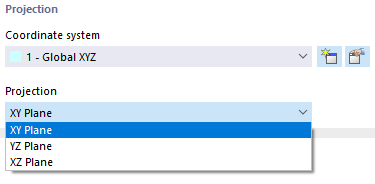
Define the "Coordinate system", then select from the "Projection" list which of the global planes XY, YZ, or XZ you want to project the reinforcement on. The projection plane must not be perpendicular to any surface with the reinforcement arranged.
Reinforcement Acting Region
If you have selected a "free reinforcement" (Free Rectangular, Free Circular, Free Polygon) as the location type, you can further specify the location of this reinforcement.
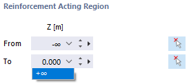
By default, the reinforcement area is indefinitely effective in the negative and positive projection directions (-∞/+∞). This way, all surfaces in the projection direction have their reinforcement defined. If you want to limit the range of the projection direction, for example, because the projection should only be active in the negative direction, you can enter the coordinate in the text box or use the
![]() button to select a suitable point in the model.
button to select a suitable point in the model.

