Member rotational restraints allow you to determine the torsional restraint around the longitudinal axis of the member or member set using components such as trapezoidal sheets or purlins. To consider the notional stiffness from a member rotational restraint, you can assign it to a member support. This chapter describes the input options for a member rotational restraint.
Rotational Restraint Type
In the list, you can select various types of rotational restraints:
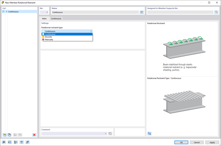
Continuous
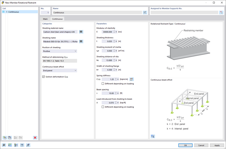
The following information is required to determine the shear panel stiffness from trapezoidal sheeting and the connection deformation:
- Sheeting material name
- Sheeting name
- Spring stiffness C100
- Load introduced from sheeting to beam
- Continuity effect
- Beam spacing
- Section deformation CD,B
You can select the material of the trapezoidal sheeting from the library by clicking the
![]() button (see the image Material Library). After selecting the material, the modulus of elasticity is transferred automatically. However, you can also define it manually.
button (see the image Material Library). After selecting the material, the modulus of elasticity is transferred automatically. However, you can also define it manually.

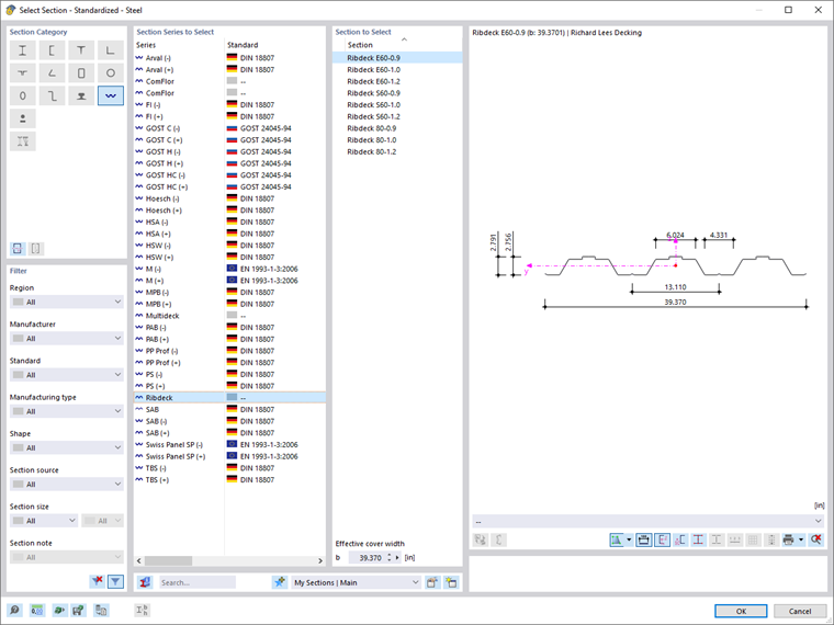
You can select the trapezoidal sheeting from the library using the
![]() button (see the image Cross-Section Library – Trapezoidal Sheeting). After selecting the trapezoidal sheeting, the position, thickness, moment of inertia, rib spacing, and the flange width of the sheeting are transferred automatically. However, you can also change them.
button (see the image Cross-Section Library – Trapezoidal Sheeting). After selecting the trapezoidal sheeting, the position, thickness, moment of inertia, rib spacing, and the flange width of the sheeting are transferred automatically. However, you can also change them.
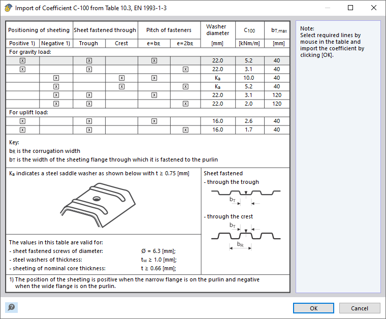
The rotational stiffness of the connection between the sheeting and the purlin CD,A is determined according to EN 1993‑1‑3. You can transfer the rotational spring stiffness C100 from Table 10.3 of EN 1993‑1‑3 by using the
![]() button (see the image Dialog Box "Import of Coefficient C-100 from Table 10.3, EN 1993-1-3"), or enter the value manually.
button (see the image Dialog Box "Import of Coefficient C-100 from Table 10.3, EN 1993-1-3"), or enter the value manually.
Furthermore, you have to define Load A, which acts between the sheeting and the purlin.
The spring stiffness CD,A as well as the Load A is assigned to all load or result combinations. Activate the "Differently depending on loading" check box to assign them by load case. Then, you can make the assignment in the Load-Dependent Properties tab (see the image Tab "Load-Dependent Properties").
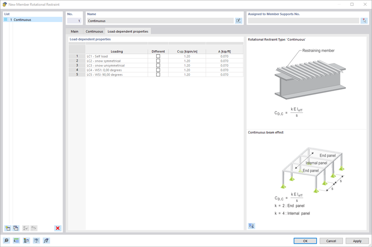
The continuity effect has an impact on the coefficient k of the rotational restraint from the cross-section deformation of the trapezoidal sheeting CD,C. For the exterior span, k = 2, and for the inner span, k = 4.
You can enter the beam spacing manually. As an alternative, you can also define this graphically by selecting the "Measure" function using the
![]() button. Finally, you can select two snap points in the work window to adopt the distance between them.
button. Finally, you can select two snap points in the work window to adopt the distance between them.
Activate the "Cross-section deformation CD,B" check box if you want to consider the rotational stiffness due to the cross-section deformation of the beam. The cross-section deformation component can only be calculated for constant I-section members, but not for tapered members or non-I-sections.
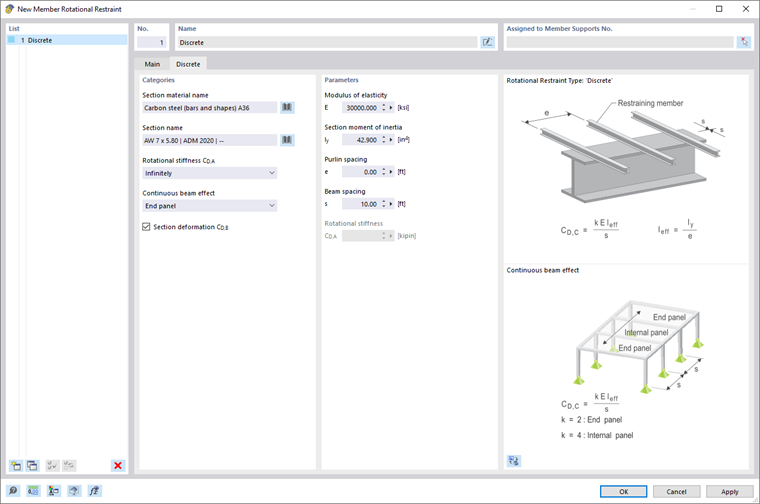
Discrete
To determine the stiffness component from single supports, for example purlins, the following specifications
are required:
- Section material name
- Section name
- Rotational stiffness CD,A
- Continuity effect
- Section deformation CD,B
- Purlin spacing
- Beam spacing
You can select the material from the library by clicking the
![]() button (see the image Material Library). After selecting the material, the modulus of elasticity is transferred automatically. However, you can also define it manually.
button (see the image Material Library). After selecting the material, the modulus of elasticity is transferred automatically. However, you can also define it manually.
You can select the cross-section from the library by clicking the
![]() button. After selecting the cross-section, the moment of inertia is transferred automatically. However, you can also change it.
button. After selecting the cross-section, the moment of inertia is transferred automatically. However, you can also change it.
You can apply the connection stiffness CD,A as an infinite value or define it manually. For the manual definition, enter the rotational stiffness CD,A directly in the "Parameters" section.
The continuity effect has an impact on the coefficient k of the rotational restraint CD,C. For the exterior span, k = 2, and for the inner span, k = 4.
Activate the "Cross-section deformation CD,B" check box if you want to consider the rotational stiffness due to the cross-section deformation of the purlin. The cross-section deformation component can only be calculated for the purlins with I-sections, but not for the purlins with non-I-sections.
You can specify the spacing of the purlins and the beam manually. As an alternative, you can also define this graphically by selecting the "Measure" function using the
![]() button. Finally, you can select two snap points in the work window to adopt the distance between them.
button. Finally, you can select two snap points in the work window to adopt the distance between them.
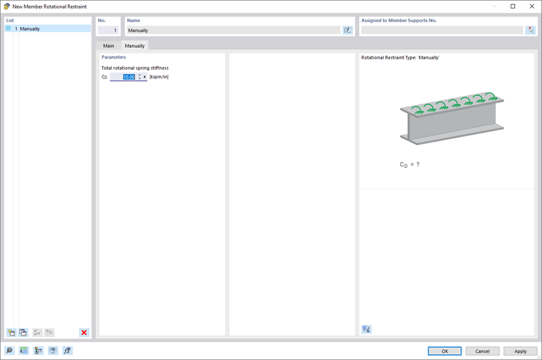
Manually
You can also manually specify the rotational spring stiffness CD.