A shear panel is taken into account when determining the elastic critical moment or the critical load factor for lateral-torsional buckling, if this is determined by the internal eigenvalue solver. A translational spring that is constant over the entire member or member set applies.
Thus, it is possible to consider the shear stiffness of a stiffening bracing or a roof cladding for the lateral-torsional buckling of the truss members.
Definition Type
Various types of shear panels are available for selection in the list:
- Trapezoidal sheeting
- Bracing
- Trapezoidal sheeting and bracing
- Defining S-prov

Defining S-prov
Currently, it is still necessary to calculate the shear panel stiffness manually. An example can be found in this technical article:
The following information is required for this:
- Shear panel stiffness
- Beam length
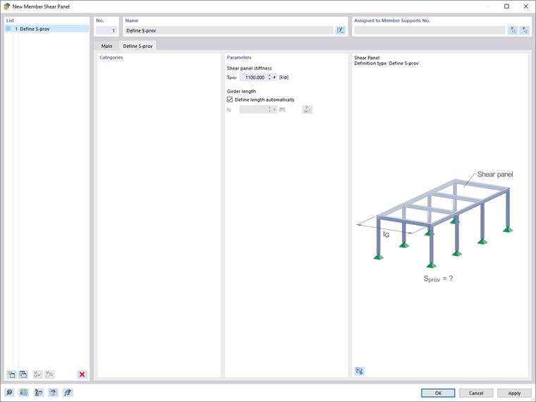
Based on the member foundation, the shear panel stiffness can be converted as follows:
The beam length is automatically adopted from the member or member set. Deactivate the "Define length automatically" check box if you want to specify the beam length manually.
Assignment to Member or Member Set
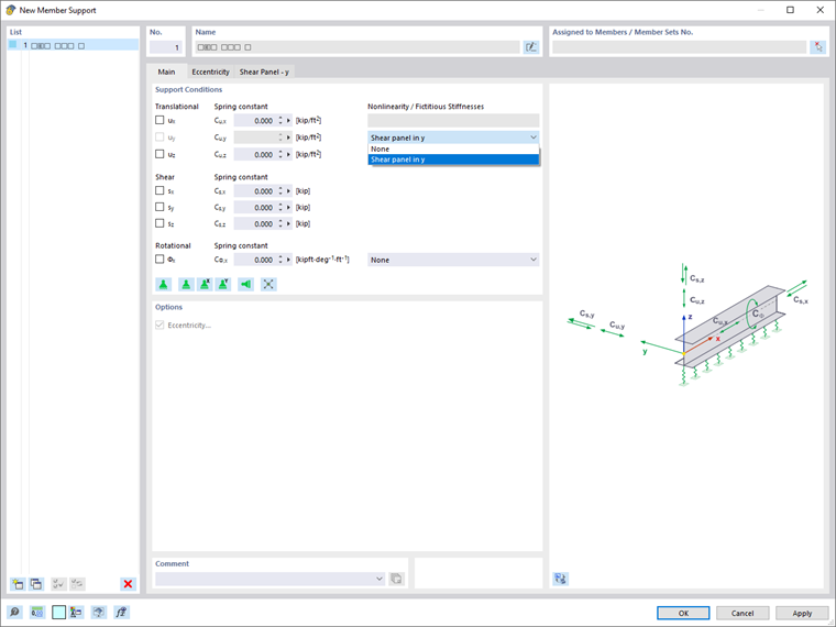
Member shear panels can be assigned to member supports. You can assign member shear panels to one or more member supports using the editing dialog box of the support. To do this, select the fictitious stiffness "Shear Panel in y" or "Shear Panel in z" in the "Nonlinearity / Fictitious Stiffnesses" list of the "Main" tab.
In the "Shear Panel – y" or "Shear Panel – z" tab, you can then assign the shear panel you want.

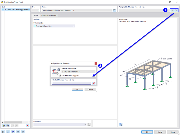
You can also graphically assign the member shear panel to a member support in the editing dialog box of the member shear panel by clicking the
![]() button. However, the shear panel needs to be already assigned to the member support.
button. However, the shear panel needs to be already assigned to the member support.
The member supports with the member shear panels defined therein are then assigned either to the members or to the higher-level member sets. Assign the member support by using the editing dialog box of the member or member set, the selection from the Member Support dialog box, or via the input table.
Position of Shear Panel on Section
You can specify the position of the shear panel on the cross-section in the "Eccentricity" tab of the "Member Support" dialog box.

Nine "Reference" check boxes symbolize distinctive locations on the cross-section. The point in the middle represents the centroid, and the eight edge points represent the intersections of the member axes y and z with the edge lines of a rectangle circumscribing the cross-section.
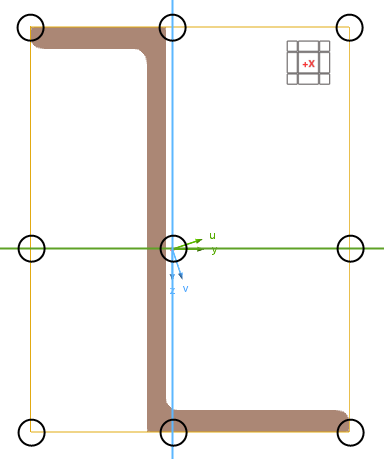
In addition to the nine check boxes, you can also use the center of gravity and the shear center as a reference point.
You can define the "offset" manually in the text boxes below. The distances refer to the local member axes y and z.
The shear panel is positioned by using the offset of the defined distance from the selected reference point at the cross-section.