.svg?mw=64&hash=343d71fbdf234f1411db2920f2dff33c0dbd6231)

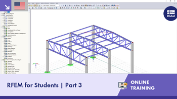
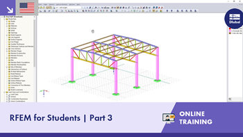
Reinforced Concrete Floor Slab
| Number of Nodes | 15 |
| Number of Lines | 6 |
| Number of Surfaces | 1 |
| Number of Load Cases | 2 |
| Number of Load Combinations | 2 |
| Dimensions (Metric) | 19.711 x 13.822 x 0.122 m |
| Dimensions (Imperial) | 64.67 x 45.35 x 0.4 feet |
| Program Version | 5.24.00 |
You can download this structural model to use it for training purposes or for your projects. However, we do not assume any guarantee or liability for the accuracy or completeness of the model.


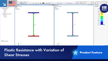


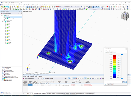
You can display the stress results within members by using clipping planes.
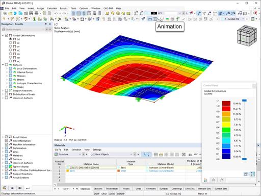
The deformation process of the global deformation components can be represented as a movement sequence.
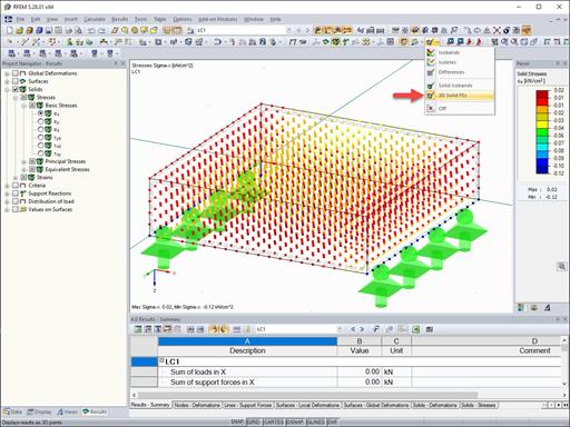
The results of solid stresses can be displayed as colored 3D points in the finite elements.
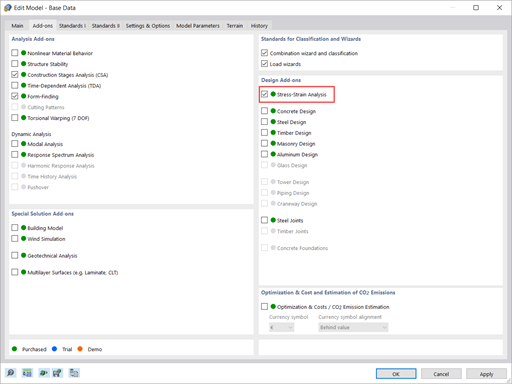
Compared to the RF‑/STEEL add-on module (RFEM 5 / RSTAB 8), the following new features have been added to the Stress-Strain Analysis add-on for RFEM 6 / RSTAB 9:
- Treatment of members, surfaces, solids, welds (line welded joints between two and three surfaces with subsequent stress design)
- Output of stresses, stress ratios, stress ranges, and strains
- Limit stress depending on the assigned material or a user-defined input
- Individual specification of the results to be calculated through freely assignable setting types
- Non-modal result details with prepared formula display and additional result display on the cross-section level of members
- Output of the design check formulas used


The new generation of 3D FEA software is used for the structural analysis of members, surfaces, and solids.

The Structure Stability add-on performs stability analysis of structures. It determines critical load factors and the corresponding stability modes.

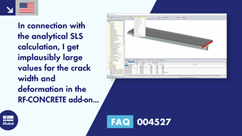
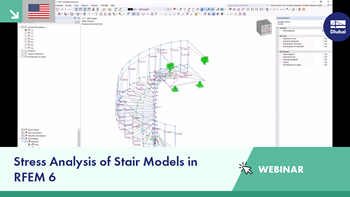
The Stress-Strain Analysis add-on performs general stress analysis by calculating the existing stresses and comparing them with the limit stresses.

The Steel Design add-on performs the ultimate and serviceability limit state design checks of steel members according to various standards.

The modern 3D structural analysis and design program is suitable for the structural and dynamic analysis of beam structures as well as the design of concrete, steel, timber, and other materials.
The Structure Stability add-on performs the stability analysis of structures. It determines critical load factors and the corresponding stability modes.
The Stress-Strain Analysis add-on performs a general stress analysis by calculating the existing stresses and comparing them to the limit stresses.
The Steel Design add-on performs the ultimate and serviceability limit state design checks of steel members according to various standards.