High-Rise Building in City Blocks


.png?mw=350&hash=ee4e41498cc6e20e1c10f0c3c1b6e177b43d290b)


In RFEM and RSTAB, you can visualize the flow field quantities of pressure, velocity, turbulence kinetic energy, and turbulence dissipation rate for the wind simulation.
The clipping planes are aligned with the respective wind direction.

In the ultimate configuration of the steel joint design, you have the option to modify the limit plastic strain for welds.

Using the "Base Plate" component, you can design base plate connections with cast-in anchors. In addition to plates and welds, the design analyzes the anchorage and the steel-concrete interaction.

In RFEM, you can generate surfaces from members with the library cross-sections as well as from the members with the RSECTION cross-section.


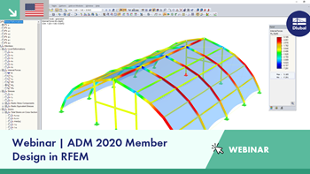
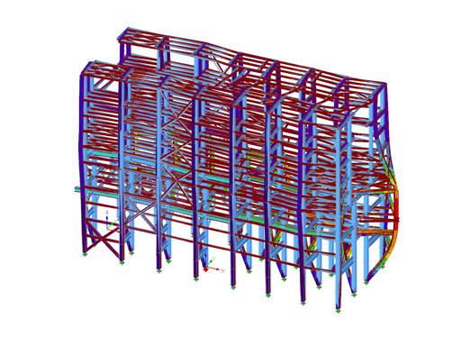
The new generation of 3D FEA software is used for the structural analysis of members, surfaces, and solids.

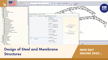
The Form-Finding add-on finds the optimal shape of members subjected to axial forces and tension-loaded surface models. The shape is determined by the equilibrium between the member axial force or the membrane stress and the existing boundary conditions.

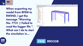
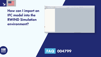
RWIND 2 is a program (digital wind tunnel) for the numerical simulation of wind flows around any building geometries with determination of the wind loads on their surfaces. It can be used as a stand-alone application or used together with RFEM and RSTAB for complete structural analysis and design.
With RWIND 2, you have a program at your side that uses a digital wind tunnel for the numerical simulation of wind flows.