
In this verification example, the capacity design values of shear forces on beams are calculated in accordance with EN 1998-1, 5.4.2.2 and 5.5.2.1 as well as the capacity design values of columns in flexure in accordance with 5.2.3.3(2). The system consists of a two span reinforced concrete beam with a span length of 5.50m. The beam is part of a frame system. The results obtained are compared with those in [1].
The Architectural Institute of Japan (AIJ) has presented a number of well-known benchmark scenarios of wind simulation.
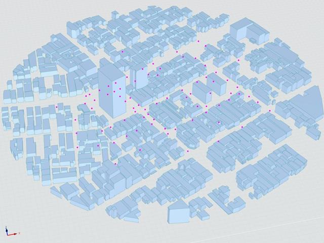
The following article deals with "Case E - Building Complex in Actual Urban Area with Dense Concentration of Low-Rise Buildings in Niigata City".
In the following, the described scenario is simulated in RWIND& 2 and the results are compared with the simulated and experimental results by AIJ.
The Architectural Institute of Japan (AIJ) has presented a number of well-known benchmark scenarios of wind simulation.
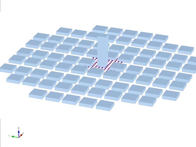
The following article deals with "Case D - High-Rise Building Among City Blocks".
In the following, the described scenario is simulated in RWIND 2 and the results are compared with the simulated and experimental results by the AIJ.
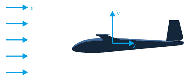
The goal of this verification example is to analyze the fluid flow around the glider. The task is to determine the drag coefficient and the lift coefficient with respect to the angle of attack. These coefficients can also be drawn into the graph of the drag polar. The limit angle for laminar fluid flow around the wing profile can also be determined from the velocity field. The available 3D CAD model (STL file) is used in RWIND 2.
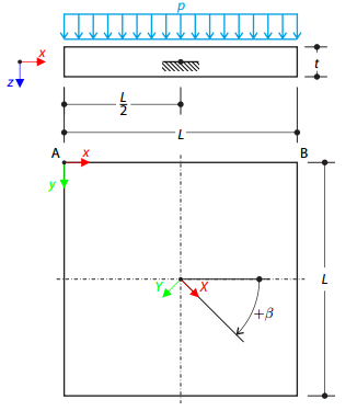
One layered square orthotropic plate is fully fixed at its middle point and subjected to pressure. Compare the deflections of the plate corners to check the correctness of the transformation.
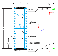
Determine the maximum deformation of a wall divided into two equal parts. The upper and lower parts are made of an elasto-plastic and an elastic material, respectively, and both end planes are restricted to move in the vertical direction. The wall's self-weight is neglected; its edges are loaded with horizontal pressure ph, and the middle plane by vertical pressure.
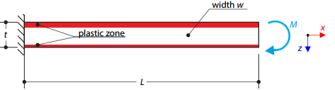
A cantilever is fully fixed on the left end and loaded by a bending moment on the right end. The material has different plastic strengths under tension and compression.
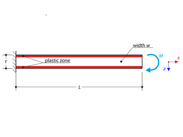
A cantilever is fully fixed on the left end and loaded by a bending moment. Plastic material is considered for the calculation.
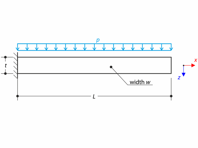
A thin plate is fully fixed on the left end and loaded by uniform pressure on the top surface.
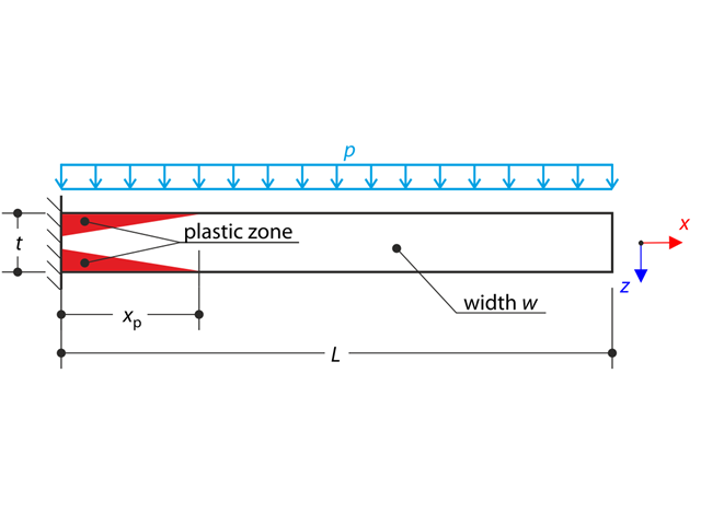
A thin plate is fully fixed on the left end and loaded by uniform pressure. Plastic material is considered for the calculation.
A cylinder made of elasto-plastic soil is subjected to triaxial test conditions. Neglecting the self-weight, the goal is to determine the limit vertical stress for shear stress failure. An initial hydrostatic stress of 100 kPa is considered.
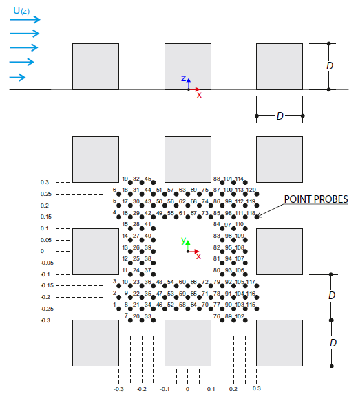
The verification example describes wind loads in several wind directions on a model of a group of buildings. The model consists of eight cubes. The velocity fields obtained by the RWIND simulation are compared with the measured values from the experiment. The experimental data are measured using a thermistor anemometer in the wind tunnel.
The verification example describes the steady-state flow around a high-rise building in city blocks (scaled model). The example is given by the Architectural Institute of Japan (AIJ). The chosen results (velocity magnitude) are compared with the measured values.
The verification example describes the steady-state flow around an isolated building (scaled model).The example is given by the Architectural Institute of Japan (AIJ). The chosen results (velocity magnitude) are compared with the measured values.
A cantilever is fully fixed on the left end and subjected to a bending moment considering plasticity.
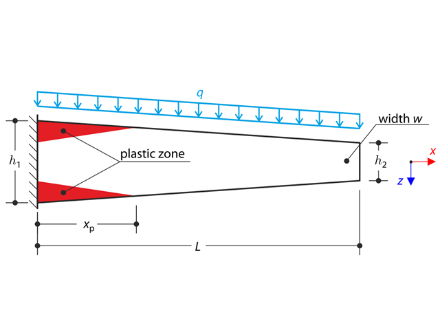
A tapered cantilever is fully fixed on the left end and subjected to a continuous load q. Small deformations are considered and the self-weight is neglected in this example. Determine the maximum deflection.
A thin plate is fully fixed on the left end and subjected to a uniform pressure. The plate is brought into the elastic-plastic state by the uniform pressure.
This verification example compares wind load calculations on a duopitch roof building using the ASCE 7-16 standard and using CFD simulation in RWIND Simulation. The building is defined according to the sketch and the inflow velocity profile taken from the ASCE 7-16 standard.

This verification example compares wind load calculations on a flat roof building using the ASCE 7-16 standard and using CFD simulation in RWIND Simulation. The building is defined according to the sketch and the inflow velocity profile taken from the ASCE 7-16 standard.
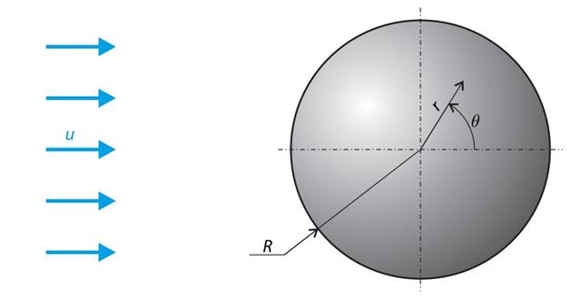
A sphere is subjected to a uniform flow of viscous fluid. The velocity of the fluid is considered at infinity. The goal is to determine the drag force. The parameters of the problem are set so that the Reynolds number is small and the radius of the sphere is also small, thus the theoretical solution can be reached - Stokes flow (G. G. Stokes 1851).
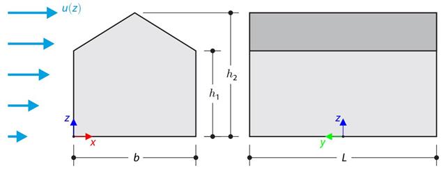
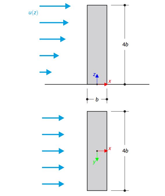
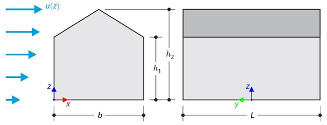
The verification example compares wind load calculation on a building with a duopitch roof using the standard EN 1991-1-4 and using CFD simulation in RWIND Simulation. The building is defined according to the sketch, and the inflow velocity profile is taken according to the standard EN 1991-1-4.
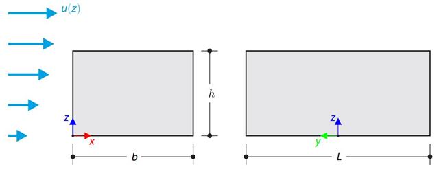
The verification example compares wind load calculation on a building with a flat roof using the standard EN 1991-1-4 and using CFD simulation in RWIND Simulation. The building is defined according to the sketch, and the inflow velocity profile is taken according to the standard EN 1991-1-4.
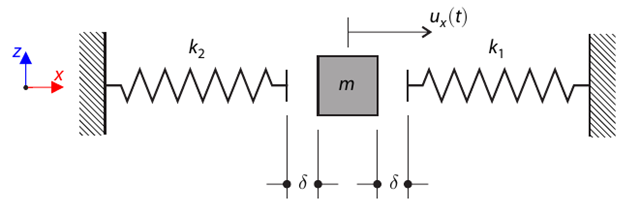
A single-mass system with clearance and two springs is initially deflected. Determine the natural oscillations of the system - deflection, velocity, and acceleration time course.
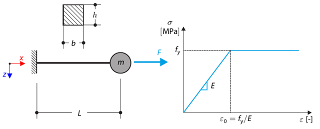
This verification example is based on Verification Example 0122. A single-mass system without damping is subjected to an axial loading force. An ideal elastic-plastic material with characteristics is assumed. Determine the time course of the end-point deflection, velocity, and acceleration.
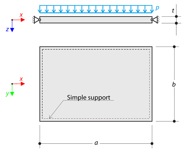
A thin rectangular orthotropic plate is simply supported and loaded by uniformly distributed pressure. The directions of axes x and y coincide with the principal directions. While neglecting self-weight, determine the maximum deflection of the plate.
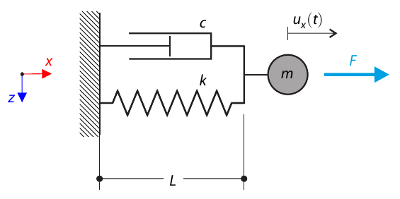
A single-mass system with dashpot is subjected to constant loading force. Determine the deflection and velocity of the dashpot endpoint in the given test time.
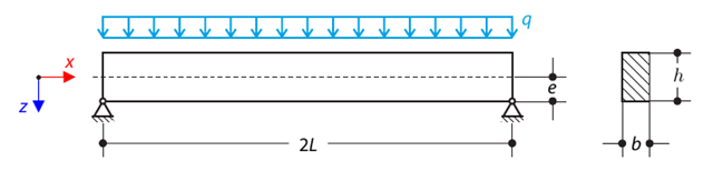
A pinned beam with a rectangular cross‑section is subjected to distributed loading and shifted vertically by eccentricity. Considering the small deformation theory, neglecting the self‑weight, and assuming that the beam is made of isotropic elastic material, determine the maximum deflection.
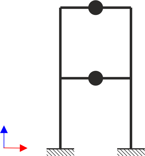
A two‑story, single‑bay frame structure is subjected to earthquake loading. The modulus of elasticity and cross‑section of the frame beams are much larger than those of the columns, so the beams can be considered rigid. The elastic response spectrum is given by the standard SIA 261/1:2003. Neglecting self-weight and assuming the lumped masses are at the floor levels, determine the natural frequencies of the structure. For each frequency obtained, specify the standardized displacements of the floors as well as equivalent forces generated using the elastic response spectrum according to the standard SIA 261/1.2003.
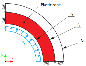
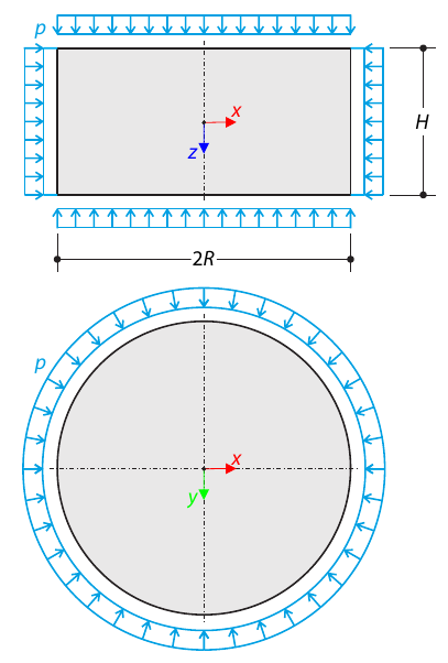
A thick-walled vessel is loaded by an inner pressure such that the vessel reaches an elastic-plastic state. While neglecting self‑weight, the analytical and numerical solutions for the radial position of the plastic zone border (under the Tresca hypothesis) are determined and compared.
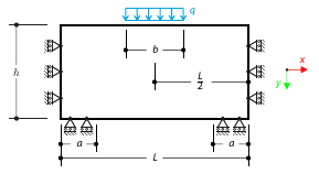
A masonry wall is exposed to a distributed load in the middle of its upper section. The Isotropic Masonry 2D material model is compared with the Isotropic Linear Elastic model, with surface stiffness property Without Tension in the nonlinear calculation.