Do you have any questions about Dlubal products or need assistance in selecting the right one for your project?
I'm here to help. You can easily reach me through the contact options provided below.
Looking forward to hearing from you!


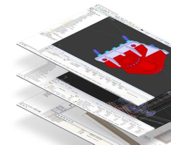
Design of Steel Members According to AS 4100-1998 (Australian Standard)
_(2)_(1).png?mw=1024&hash=ed67cf492a6214a737cf416b358242cedd959ab6)
RF-/STEEL AS | Features
- Design of members and sets of members for tension, compression, bending, shear, combined internal forces, and torsion
- Stability analysis of buckling and lateral-torsional buckling
- Automatic determination of critical buckling loads and critical buckling moments for general load applications and support conditions by means of a special FEA program (eigenvalue analysis) integrated in the module
- Alternative analytical calculation of the critical buckling moment for standard situations
- Optional application of discrete lateral supports to beams and continuous members
- Automatic cross-section classification (compact, noncompact, and slender)
- Serviceability limit state design (deflection)
- Cross-section optimization
- A wide range of available cross-sections, such as rolled I-sections, channel sections, T-sections, angles, rectangular and circular hollow sections, round bars, symmetrical, asymmetrical, parameterized I-, T-, and angle sections, as well as user-defined SHAPE‑THIN sections
- Clearly arranged input and result windows
- Detailed result documentation including references to design equations of the used standard
- Various filter and sorting options of results including result lists by member, cross-section, x-location, or by load cases, load and result combinations
- Result table of member slenderness and governing internal forces
- Parts list with weight and solid specifications
- Seamless integration in RFEM/RSTAB
- Metric and imperial units
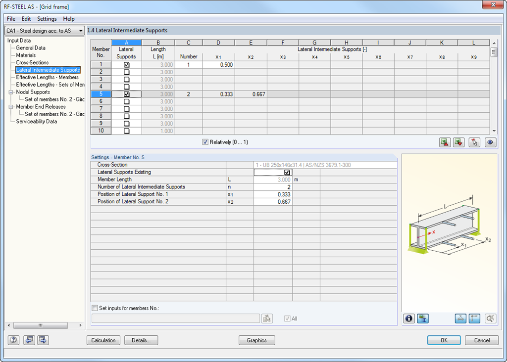
Working with RF-/STEEL AS
First, you have to select the load cases, load combinations, and result combinations to be designed.
Further specifications include presetting of lateral intermediate supports, effective lengths, and other standard-specific design parameters. In the case of continuous members, it is possible to define individual support conditions and eccentricities of each intermediate node of single members. A special FEA tool then determines the critical loads and moments required for the stability analysis in these situations.
In connection with RFEM/RSTAB, it is possible to apply the Direct Analysis Method taking into account the influence of the general calculation according to the second-order analysis. In this way, you avoid using special enlargement factors.
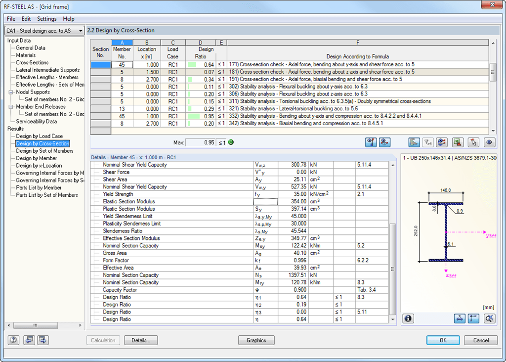
RF-/STEEL AS | Results
The first window shows the maximum design ratios including the corresponding design of each designed load case, load combination, or result combination.
The other result windows list all detailed results sorted by specific subject in extendable tree menus. All intermediate results along the members can be displayed at any location. In this way, you can easily retrace how the module has performed the individual designs.
The complete module data are part of the RFEM/RSTAB printout report. You can select the report contents and extent specifically for the individual designs.
.png?mw=192&hash=f63e4a3f1836233005de32f60201d5392e507cf1)
Calculate Your Price
The price is valid for United States. Prices are only valid for the software usage in United States. You can get exact prices after signing in. Please log on to your account at Dlubal Software to generate an updated quote.
Implemented Standards for Reinforced Concrete Design
Standards for Concrete Design
Annexes for EN 1992-1-1


RFEM and RSTAB models can be saved as 3D glTF models (*.glb and *.glTF formats). View the models in 3D in detail with a 3D viewer from Google or Babylon. Take your VR glasses, such as Oculus, to "walk" through the structure.
You can integrate the 3D glTF models into your own websites using JavaScript according to these instructions (as on the Dlubal website Models to Download).

With the Camera Fly Mode view option, you can fly through your RFEM and RSTAB structure. Control the direction and speed of the flight with your keyboard. Additionally, you can save the flight through your structure as a video.

The direct interface with Revit allows you to update the Revit model according to the changes you have made in RFEM or RSTAB. Depending on the modification, the Revit objects may have to be regenerated (deleting the object and subsequent regeneration). The regeneration is performed on the basis of the RFEM/RSTAB model.
If you want to avoid this regeneration, activate the check box 'Update only materials, thicknesses, and sections'. In this case, only the properties of the objects will be adjusted. Changes different from those in material, surface thickness, and section are, however, not considered in this case.

The reinforcement proposal from RF-/CONCRETE Members can be exported to Revit. The rectangular and circular cross-sections are currently supported.
The reinforcement bars can be modified retroactively in Revit.


