Eurocode 2 | Reinforced Concrete Structures According to DIN EN 1992-1-1
With online group training at Dlubal, you can enhance your professional knowledge, and you will ensure that your investment in the software pays off to the maximum.
Eurocode 2 | Reinforced Concrete Structures According to DIN EN 1992-1-1
2022-02-23
8:30 AM- 12:30 PM CET
German
Price
250.00 EUR plus VAT
The application of the add-ons for the design according to EC 2 will be explained using selected practical examples.
This training explains the design of reinforced concrete structures according to the standard DIN EN 1992‑1‑1 by using the structural analysis software RFEM and the relevant add-on modules.
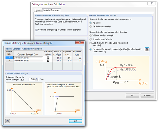
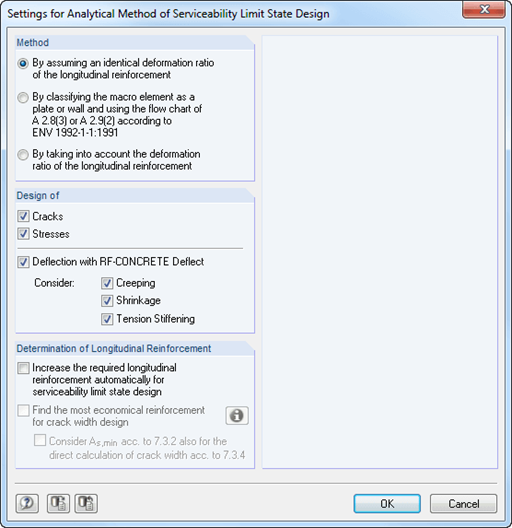
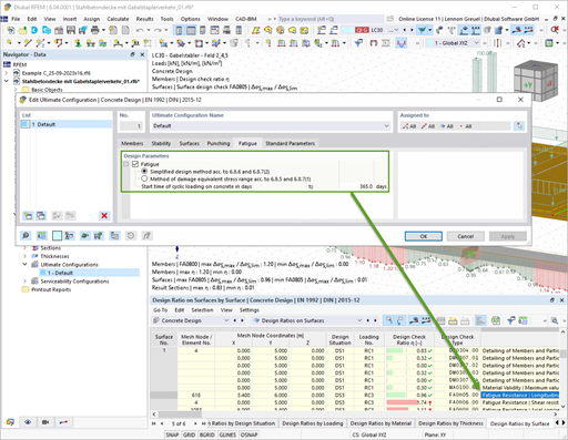
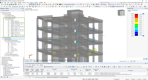
The application of the add-on modules for the design according to EC 2 will be explained using selected practical examples. The ultimate limit state (ULS), serviceability limit state (SLS), stability analysis, and punching are covered.
Time Schedule
-
Basics in General
Presentation of RFEM 6
-
Combinatorics
Combinations for the ultimate and serviceability limit states
-
Basics of Member Design
Design specifications for frame structures
Evaluation of results
-
Basics of Surface Design
Design specifications for surface structures
Evaluation of results
-
Punching Shear Design
Design specifications for punching shear locations
Evaluation of results
-
Serviceability Limit State Design
Settings for serviceability limit state design for member and surface structures
-
Stability Analysis
Stability analysis according to the nominal curvature method
-
Tips & Tricks
The online training is carried out in RFEM with the corresponding add-ons.
A reliable internet connection is required to participate. Basic knowledge of RSTAB or RFEM is also expected. The online training is carried out in RFEM with the associated add-on modules.
During the training, each participant can ask questions via chat at any time.
After the training, each participant receives:
Training certificate
Training presentation to download
Used models to download
Video recording of the training
This way, the participant can go through and understand the training step by step on the models.
To take part in the online training, the participant will receive the login information in due time.
Dipl.-Ing. (FH) Paul Kieloch
Product Engineering & Customer Support
Mr. Kieloch provides technical support to our customers and is responsible for development in the area of reinforced concrete structures.
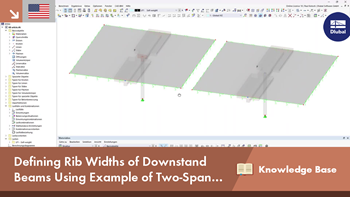
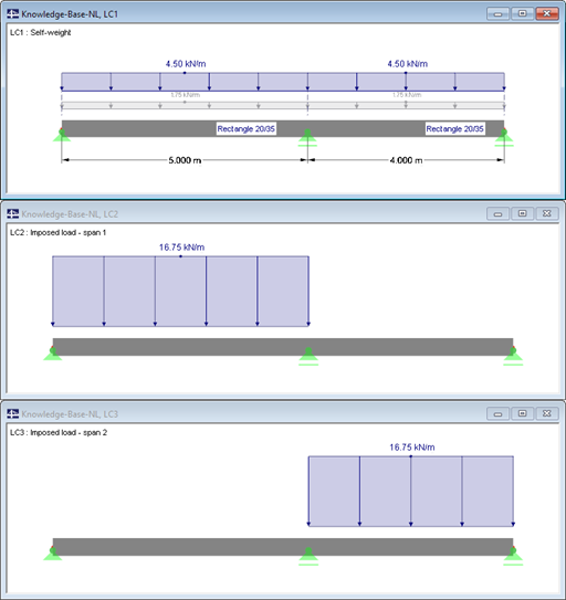
When determining the minimum reinforcement for the serviceability limit state according to 7.3.2, the applied effective tensile strength fct,eff has a significant influence on the determined amount of reinforcement. The following article gives an overview about determining the effective tensile strength fct,eff and the input options in RF-CONCRETE.
The RF-CONCRETE Members and CONCRETE add-on modules provide the option for "Dimensioning of Longitudinal Reinforcement for Serviceability Limit State". You can select the design criteria for the calculation of the longitudinal reinforcement.
When designing reinforced concrete components according to EN 1992‑1‑1 [1], nonlinear methods of determining internal forces for the ultimate and serviceability limit states are possible. In this case, the internal forces and deformations are determined with respect to their nonlinear behaviour. The analysis of stresses and strains in cracked state usually provides the deflections, which clearly exceed the linearly determined values.
In order to correctly design a downstand beam or a T-beam in RFEM 6 using the Concrete Design add-on, it is essential to determine the flange widths for the rib members. This article describes the input options for a two-span beam and the calculation of the flange dimensions according to EN 1992-1-1.
The nonlinear calculation is activated by selecting the design method of the serviceability limit state. You can individually select the analyses to be performed as well as the stress-strain diagrams for concrete and reinforcing steel. The iteration process can be influenced by these control parameters: convergence accuracy, maximum number of iterations, arrangement of layers over cross-section depth, and damping factor.
You can set the limit values in the serviceability limit state individually for each surface or surface group. Allowable limit values are defined by the maximum deformation, the maximum stresses, or the maximum crack widths. The definition of the maximum deformation requires additional specification as to whether the non-deformed or the deformed system should be used for the design.
RF-CONCRETE Members
The nonlinear calculation can be applied to the ultimate and the serviceability limit state designs. In addition, you can specify the concrete tensile strength or the tension stiffening between the cracks. The iteration process can be influenced by these control parameters: convergence accuracy, maximum number of iterations, and damping factor.
The deformation analysis according to the approximation method defined in standards (for example, deformation analysis according to EN 1992‑1‑1, 7.4.3) applies to the calculation of "effective stiffnesses" in the finite elements in accordance with the existing limit state of the concrete with or without cracks. These stiffnesses are used to determine the surface deformation by repeated FEM calculation.
The effective stiffness calculation of finite elements takes into account a reinforced concrete cross-section. Based on the internal forces determined for the serviceability limit state in RFEM, the program classifies the reinforced concrete cross-section as 'cracked' or 'uncracked'. If the tension stiffening at a section should be considered as well, a distribution coefficient (according to EN 1992-1-1, Eq. 7.19, for example) is used. The material behavior for the concrete is assumed to be linear-elastic in the compression and tension zone until the concrete tensile strength is reached. This is reached exactly in the serviceability limit state.
When determining the effective stiffnesses, creep and shrinkage are taken into account at the "cross-section level". The influence of shrinkage and creep in statically indeterminate systems is not taken into account in this approximation method (for example, tensile forces from shrinkage strain in systems restrained on all sides are not determined and must be considered separately). In summary, RF-CONCRETE Deflect calculates deformations in two steps:
Calculation of effective stiffnesses of the reinforced concrete cross-section assuming linear-elastic conditions
Calculation of the deformation using the effective stiffnesses with FEM
With the Concrete Design add-on, you can perform the fatigue design of members and surfaces according to EN 1992‑1‑1, Chapter 6.8.
For the fatigue design, you can optionally select two methods or design levels in the design configurations:
Design Level 1: Simplified design according to 6.8.6 and 6.8.7(2): The simplified design is performed for frequent action combinations according to EN 1992‑1‑1, Chapter 6.8.6 (2), and EN 1990, Eq. (6.15b) with the traffic loads relevant in the serviceability state. A maximum stress range according to 6.8.6 is designed for the reinforcing steel. The concrete compressive stress is determined by means of the upper and lower allowable stress according to 6.8.7(2).
Design Level 2: Design of damage equivalent stress acc. to 6.8.5 and 6.8.7(1) (simplified fatigue design): The design using damage equivalent stress ranges is performed for the fatigue combination according to EN 1992‑1‑1, Chapter 6.8.3, Eq. (6.69) with the specifically defined cyclic action Qfat.
The Concrete Design add-on allows you to perform the seismic design of reinforced concrete members according to EC 8. This includes, among other things, the following functionalities:
Seismic design configurations
Differentiation of the ductility classes DCL, DCM, DCH
Option to transfer the behavior factor from a dynamic analysis
Check of the limit value for the behavior factor
Capacity design checks of "Strong column - weak beam"
Detailing and particular rules for curvature ductility factor
Detailing and particular rules for local ductility
The Concrete Design add-on allows for various design checks according to international standards. You can design members, surfaces, and columns, as well as perform punching and deformation analyses.
The Construction Stages Analysis (CSA) add-on allows for considering the construction process of structures (member, surface, and solid structures) in RFEM.
In RFEM, the Geotechnical Analysis add-on uses properties from soil samples to determine the soil body to be analyzed. The accurate determination of soil conditions significantly affects the quality of the structural analysis of buildings.
The Response Spectrum Analysis add-on performs seismic analysis using multi-modal response spectrum analysis. The spectra required for this can be created in compliance with the standards or can be user-defined. The equivalent static forces are generated from them. The add-on includes an extensive library of accelerograms from seismic zones that can be used to generate the response spectra.
Using the Pushover Analysis add-on, you can analyze the seismic actions on a particular building, and thus assess whether the building can withstand an earthquake.
The Building Model add-on for RFEM allows you to define and manipulate a building using stories. The stories can be adjusted in many ways afterwards. The information about stories and the entire model (center of gravity) is displayed in tables and graphics.
The Masonry Design add-on for RFEM allows you to design masonry using the finite element method. It was developed as part of the research project titled DDMaS – Digitizing the Design of Masonry Structures. The material model represents the nonlinear behavior of the brick-mortar combination in the form of macro-modeling.