Question
Is it also possible to design individual hollow sections using the HSS add‑on module?
Answer:
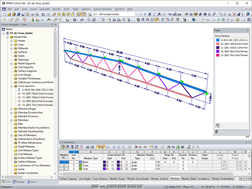
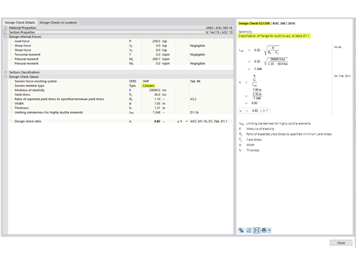
The standard EN 1993‑1‑8 specifies which kinds of cross-sections can be considered. The designs are interpreted in such a way that only one wall thickness is possible for a cross-section. If there is an invalid cross-section, the corresponding message is displayed (see Image 01). Therefore, the question about the extension for such cross-sections must be answered in the negative. The standard is largely based on tests / research. Therefore, the focus is on hot-finished hollow sections according to EN 10210 and cold-formed hollow sections according to EN 10219.
Do you have any questions?
This technical article deals with the design of structural components and cross-sections of a welded truss girder in the ultimate limit state. Furthermore, the deformation analysis in the serviceability limit state is described.
The three types of moment frames (Ordinary, Intermediate, Special) are available in the Steel Design add-on of RFEM 6. The seismic design result according to AISC 341-22 is categorized into two sections: member requirements and connection requirements.
The Steel Design add-on in RFEM 6 now offers the ability to perform seismic design according to AISC 341-16 and AISC 341-22. Five types of seismic force-resisting systems (SFRS) are currently available.
The three types of moment frames (Ordinary, Intermediate, Special) are available in the Steel Design add-on of RFEM 6. The seismic design result according to AISC 341-16 is categorized into two sections: member requirements and connection requirements.
In the ultimate configuration of the steel joint design, you have the option to modify the limit plastic strain for welds.
The "Base Plate" component allows you to design base plate connections with cast-in anchors. In this case, plates, welds, anchorages, and steel-concrete interaction are analyzed.
In the "Edit Section" dialog box, you can display the buckling shapes of the Finite Strip Method (FSM) as a 3D graphic.
- Design of five types of seismic force-resisting systems (SFRS) includes Special Moment Frame (SMF), Intermediate Moment Frame (IMF), Ordinary Moment Frame (OMF), Ordinary Concentrically Braced Frame (OCBF), and Special Concentrically Braced Frame (SCBF)
- Ductility check of the width-to thickness ratios for webs and flanges
- Calculation of the required strength and stiffness for stability bracing of beams
- Calculation of the maximum spacing for stability bracing of beams
- Calculation of the required strength at hinge locations for stability bracing of beams
- Calculation of the column required strength with the option to neglect all bending moments, shear, and torsion for overstrength limit state
- Design check of column and brace slenderness ratios
Recommended Products for You