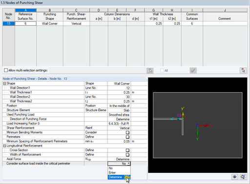
Question
Is it possible to calculate the punching shear reinforcement for a fixed value of a longitudinal reinforcement in RF‑PUNCH Pro?
Fabio is in charge of technical and commercial management of the Italian branch office of Dlubal Software. He also provides technical support and sales assistance, and contributes to the continuous development of the programs for the Italian market.
The punching load can be determined from a single load (from column/loading/nodal support) and the smoothed or unsmoothed shear force distribution along the control perimeter, or it can be defined by the user.
Since the module is fully integrated in RFEM, all nodes of punching shear on the reference surface are known. Therefore, you can check for collision of the determined perimeters with those of the neighboring columns.
After opening the module, the materials and surface thicknesses defined in RFEM are preset. The nodes to be designed are automatically recognized but can also be modified by the user.
It is possible to consider openings in the area with risk of punching shear. The openings can be transferred from RFEM or specified only in RF‑PUNCH Pro so they do not effect the stiffnesses of the RFEM model.
The parameters of the longitudinal reinforcement are the number and direction of the layers and the concrete cover, specified separately for the top and bottom of the slab on a surface-by-surface basis.
The next input window allows you to define all additional details for nodes of punching shear.
The module recognizes the position of the punching node and automatically sets, whether the node is located in the center of the slab, on the slab edge or in the slab corner.
In addition, it is possible to set punching load, load increment factor β, and the existing longitudinal reinforcement. Optionally, the minimum moments can be activated for determining the required longitudinal reinforcement and enlarged column head.
To facilitate orientation, a slab is always displayed with the corresponding node of punching shear. You can also open the design program by HALFEN, a German producer of shear rails. All RFEM data can be imported to this program for further easy and effective processing.
- Import of relevant information and results from RFEM
- Integrated, editable material and section library
- The module extension EC2 for RFEM enables the design of reinforced concrete members according to EN 1992‑1‑1:2004 (Eurocode 2) and the following National Annexes:
- DIN EN 1992-1-1/NA/A1:2015-12 (Germany)
- ÖNORM B 1992-1-1:2018-01 (Austria)
- NBN EN 1992-1-1 ANB:2010 (Belgium)
- BDS EN 1992-1-1:2005/NA:2011 (Bulgaria)
- EN 1992-1-1 DK NA:2013 (Denmark)
- NF EN 1992-1-1/NA:2016-03 (France)
- SFS EN 1992-1-1/NA:2007-10 (Finland)
- UNI EN 1992-1-1/NA:2007-07 (Italy)
- LVS EN 1992-1-1:2005/NA:2014 (Latvia)
- LST EN 1992-1-1:2005/NA:2011 (Lithuania)
- MS EN 1992-1-1:2010 (Malaysia)
- NEN-EN 1992-1-1+C2:2011/NB:2016 (Netherlands)
- NS EN 1992-1 -1:2004-NA:2008 (Norway)
- PN EN 1992-1-1/NA:2010 (Poland)
- NP EN 1992-1-1/NA:2010-02 (Portugal)
- SR EN 1992-1-1:2004/NA:2008 (Romania)
- SS EN 1992-1-1/NA:2008 (Sweden)
- SS EN 1992-1-1/NA:2008-06 (Singapore)
- STN EN 1992-1-1/NA:2008-06 (Slovakia)
- SIST EN 1992-1-1:2005/A101:2006 (Slovenia)
- UNE EN 1992-1-1/NA:2013 (Spain)
- CSN EN 1992-1-1/NA:2016-05 (Czech Republic)
- BS EN 1992-1-1:2004/NA:2005 (United Kingdom)
- TKP EN 1992-1-1:2009 (Belarus)
- CYS EN 1992-1-1:2004/NA:2009 (Cyprus)
In addition to the National Annexes (NA) listed above, you can define a specific NA, applying user‑defined limit values and parameters.
- Sensible and complete presetting of input parameters
- Punching design on columns, wall ends, and wall corners
- Optional arrangement of an enlarged column head
- Automatic recognition of the position of the punching node from the RFEM model
- Detection of curves or splines as boundary of the control perimeter
- Automatic consideration of all slab openings defined in the RFEM model
- Structure and graphical display of the control perimeter before calculation starts
- Qualitative determination of punching shear reinforcement
- Optional design with unsmoothed shear stress along the control perimeter that corresponds to the actual shear stress distribution in the FE model
- Determination of the load increment factor β via full-plastic shear distribution as constant factors according to EN 1992‑1‑1, Sect. 6.4.3 (3), based on EN 1992‑1‑1, Fig. 6.21N or by user‑defined specification
- Integration of design software by Halfen, a producer of shear rails
- Numerical and graphical display of results (3D, 2D, and in sections)
- Punching shear design with or without punching shear reinforcement
- Optional consideration of minimum moments according to EN 1992‑1‑1 when determining longitudinal reinforcement
- Design or analysis of longitudinal reinforcement
- Complete integration of results in the RFEM printout report
After the design, the punching checks are presented clearly and with all result details, so that traceability is guaranteed at all times. The provided and allowable shear stresses for the shear resistance design of a slab as well as various perimeters and reinforcement ratios are represented in detail. If necessary, a clarifying note is displayed.
The next result window lists the required longitudinal or punching reinforcement of each analyzed node. An explanatory graphic is also available. The design results can be clearly displayed with values in the work window. Furthermore, you can add all result tables and graphics into the global printout report of RFEM, which guarantees coherent documentation.