Question
Why is the imperfection always displayed graphically with a displacement at the column base?
Answer:
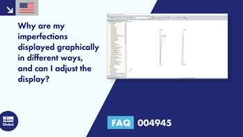
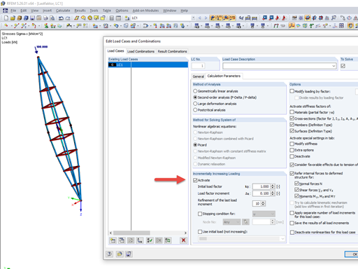
In the graphic, imperfections are always oriented on a support. In the attached model and in Image 01, the only support of the imperfection is defined at the column head. Therefore, the imperfection is oriented at this point.Since the graphical imperfection is in fact an equivalent load, the display is only of visual relevance in this case. The display is not important for the calculation.
In order to orient the imperfection graphically to the upper column head, you could use a rigid member, for example, and arrange the support there (Image 02).
Do you have any questions?
RFEM and RSTAB can calculate the critical load factor for each load case (LC) and each load combination (CO) in the case of a geometrically nonlinear calculation (second-order analysis and following).
Very small torsional moments in the members to be designed often prevent certain design formats. In order to neglect them and still perform the designs, you can define a limit value in RF‑/STEEL EC3 from which torsional shear stresses are taken into account.
Structure stability is not a new phenomenon when referring to steel design. The Canadian steel design standard CSA S16 and the most recent 2019 release are no exception. Detailed stability requirements can be addressed with either the Simplified Stability Analysis Method in Clause 8.4.3 or, new to the 2019 standard, the Stability Effects in Elastic Analysis method provided in Annex O.
The RF‑/STEEL EC3 add-on module automatically transfers the buckling line to be used for the flexural buckling analysis for a cross-section from the cross-section properties. The assignment of the buckling line can be adjusted manually in the module input for general cross-sections in particular, as well as for special cases.
In RFEM, the oriented strand board (OSB) material is available for the USA and Canada. The material parameters are taken from the "Panel Design Specification manual".
The "Bracing in Cells" function allows you to generate diagonal bracing with just a few clicks. You can find this feature under Tools → Generate Model – Members → Bracing in Cells.
In RFEM and RSTAB, you can visualize the flow field quantities of pressure, velocity, turbulence kinetic energy, and turbulence dissipation rate for the wind simulation.
The clipping planes are aligned with the respective wind direction.
In the ultimate configuration of the steel joint design, you have the option to modify the limit plastic strain for welds.
What could be the reason?
Recommended Products for You