9 Results
View Results:
Sort by:
Structures react differently to wind action depending on stiffness, mass, and damping. A basic distinction is made between buildings that are prone to vibration and those that are not.

According to Clause 7.3.2 (2), standard DIN EN 1992-1-1 requires: "In profiled cross‑sections like T‑beams and box girders, the minimum reinforcement should be determined for the individual parts of the section (webs, flanges)." In the case of a floor beam with a T‑section, the minimum reinforcement should be determined for both flanges and the web if the corresponding partial cross‑sections are in the tension area. Image 01 shows the division into partial cross-sections.
![Time-Dependent Settlement Components [2]](/en/webimage/009673/2419908/01-en-png-png.png?mw=640&hash=5e657e3feb5c1bb6d21727468dd85d91e1c9f29f)
For the serviceability limit state design according to Section 6.6 of Eurocode EN 1997‑1, settlement has to be calculated for spread foundations. RF-/FOUNDATION Pro allows you to perform the settlement calculation for a single foundation. For this, you can chose between an elastic and a solid foundation. By defining a soil profile, it is possible to consider several soil layers under the foundation base. The results of the settlement, foundation tilting, and vertical soil contact stress distribution are displayed graphically and in tables to provide a quick and clear overview of the calculation performed. In addition to the design of the foundation settlement in RF-/FOUNDATION Pro, the structural analysis determines the representative spring constants for the support and can be exported to the structural model of RFEM or RSTAB.
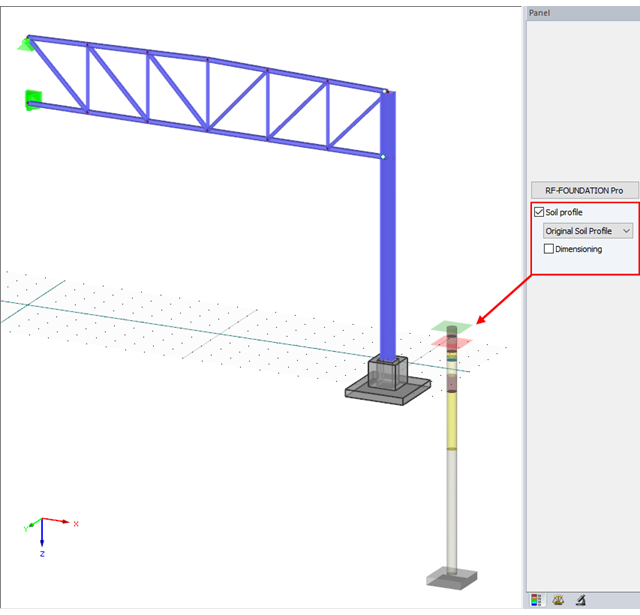
With version x.06.1103, the input of a soil profile was introduced in RF-/FOUNDATION Pro.
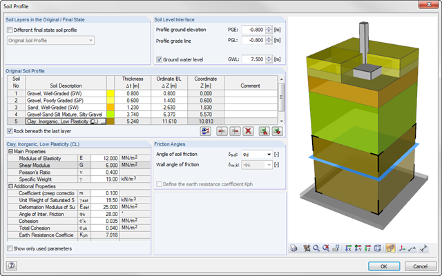
As of program version x.06.1103, you can enter a soil profile in RF‑/FOUNDATION Pro. This gives you the advantage of setting several soil layers with different soil parameters above and below the foundation base. To enter the soil layers, there is a library with various soil types that can also be extended with user‑defined soils. The user-defined soil profile is shown in an interactive information graphic. Any change (for example, a soil thickness modification) is reflected in the graphic immediately.
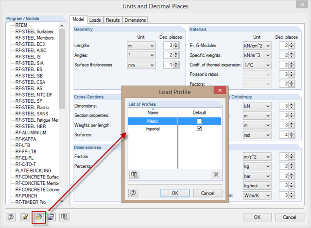
When changing the units from the metric to the imperial measurement system, it is not necessary to change all the units individually. To do this, corresponding unit profiles are available in the "Units and Decimal Places" dialog box, which you can activate as shown in the picture.
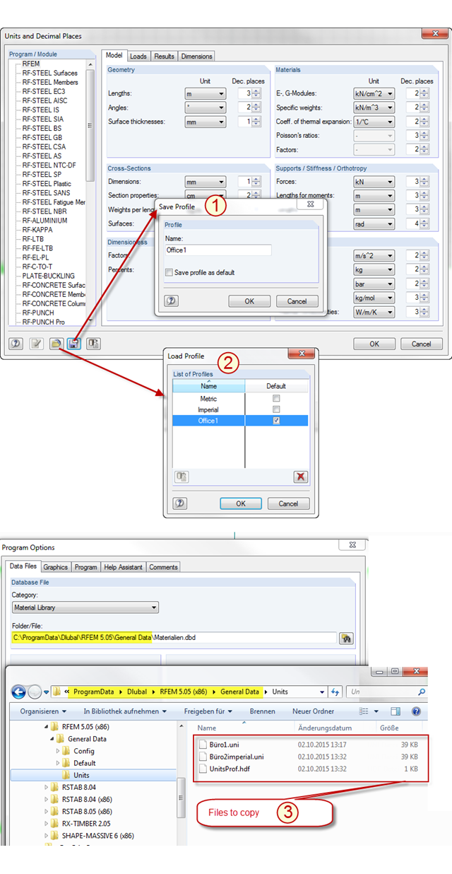
In RFEM and RSTAB, there are two predefined unit profiles available by default. These profiles cover the metric and the imperial systems of measurement. You can individually adjust the units predefined by Dlubal Software, including the decimal places used. To avoid losing the changes you have made, you can save a new profile for the units (see Item [1] in the picture). The stored profile can be loaded again (see Item [2] in the picture) or transferred from PC to PC. To do this, simply copy the content of the "Units" folder in the RFEM or RSTAB file directory from one PC to another (see Item [3] in the picture). In this way, you can achieve an office standard regarding the units used in all your workplaces.
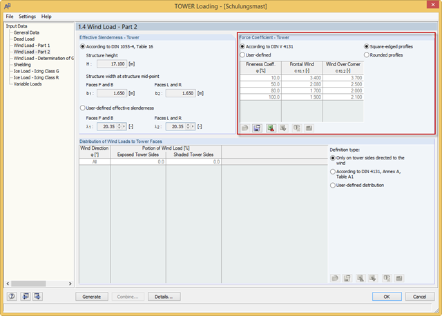
RF-/TOWER load was extended with force coefficients for rounded profiles of four-sided towers and square-edged profiles of three-sided towers. The force coefficients for rounded profiles are determined using the Reynolds number. Previously, you could only use the rounded profiles for four‑sided towers and the square‑edged profiles for three‑sided towers.
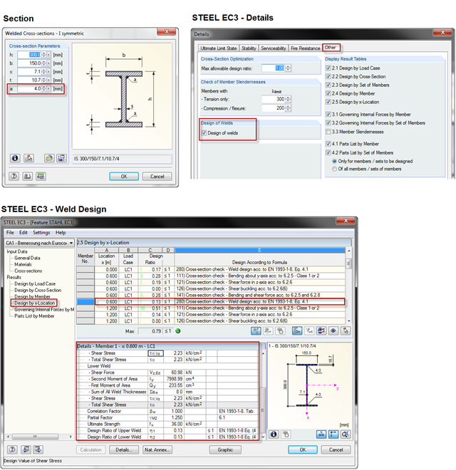
When using a welded profile, weld seam verification can also be carried out in RF-/STEEL EC3 as part of the design. The program performs the typical designs according to EN 1993‑1‑8.