467 Results
View results:
Sort by:

This article describes and explains the influence of bending stiffness of cables on their internal forces. Furthermore, the text provides information on how this influence can be reduced.

Using the Timber Design add-on, timber column design is possible according to the 2018 NDS standard ASD method. Accurately calculating timber member compressive capacity and adjustment factors is important for safety considerations and design. The following article will verify the maximum critical buckling strength calculated by the Timber Design add-on using step-by-step analytical equations as per the NDS 2018 standard including the compressive adjustment factors, adjusted compressive design value, and final design ratio.

Rolled sections, the most common cross‑section type in RFEM and RSTAB, can also have user‑defined parameters. To do this, select the cross‑section to be modified in the cross‑section library and click the [Parametric Input...] button.

In this article, the adequacy of a 2x4 dimension lumber subject to combined biaxial bending and axial compression is verified using the RF-/TIMBER AWC add-on module. The beam-column properties and loading are based on example E1.8 of AWC Structural Wood Design Examples 2015/2018.

The add-on modules for designing structural member components according to national, European, and international standards also show design results in addition to numerical output in tables graphically, as diagrams displayed on the framework.

In RFEM and RSTAB, there are various options to renumber the individual structural elements, such as nodes, lines, members, surfaces, or solids. Two options are available for renumbering: singly and automatically.
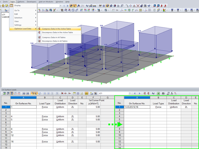
To ensure the well‑arranged structure of data in tables, the load data are organized automatically in RFEM and RSTAB.
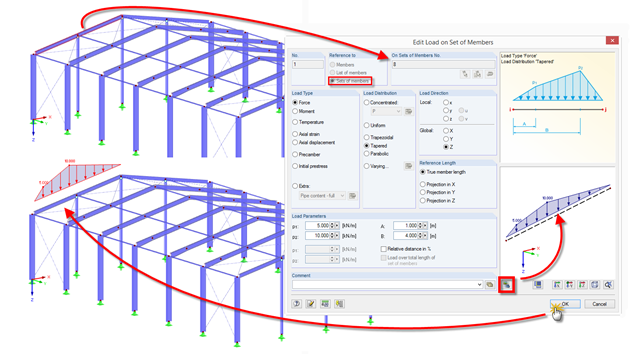
RFEM and RSTAB provide a helpful preview to check the input of member and line loads in the dialog box.

In RFEM and RSTAB, parametrization provides you with many options, especially for recurring structural elements. Within the parametrization tool, you can access the internal values of a model; for example, the values of a selected cross‑section. The following example shows how this can work.

RFEM and RSTAB can calculate the critical load factor for each load case (LC) and each load combination (CO) in the case of a geometrically nonlinear calculation (second-order analysis and following).
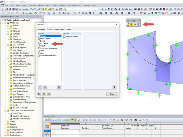
The tools arrangement in the workplace can make your work fast and efficient.
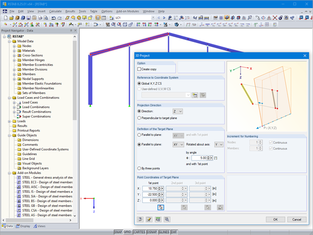
If you want to only change a few geometry parameters in a model, it is not always necessary to remove these structural parts and redefine them.

If members aligned in space meet in a node, the local x- or y-axes of the members do not lie in one plane, since the local z-axes are aligned in the plane of gravity.
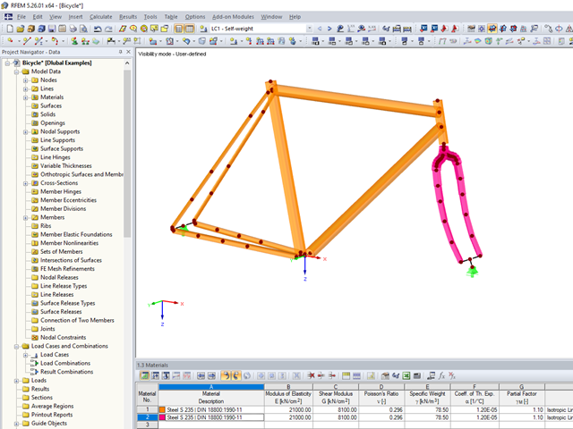
In RFEM and RSTAB, you can simulate extensive complex models from different materials in one computing environment.

If you want to consider guide objects in the overall view (F8 key or double-click on the mouse wheel) or, for example, in a particular direction of the views, you can enable this option in the settings of the particular guide objects (guidelines, background layers, line grids).

Foundations including dimensions can be saved as a template in a user-defined database.

It is possible to edit a reinforcement layout or an existing reinforcement directly in the reinforcement's 3D rendering.

In RFEM 5 as well as RSTAB 8 in RF-/FOUNDATION Pro, you can save the foundation dimensions for all five foundation types as foundation templates in a user-defined database and use them later in other models.

In RF-/FOUNDATION Pro, the foundation design requires the definition of the corresponding loading (load cases, load combinations, or result combinations) for different design situations (STR, GEO, UPL, or EQU).

The dialog box for editing load or result combinations is a non-modal dialog box. This means that after you open this dialog box, you can edit the combinations outside the dialog box as well. For manually defining or editing a combination, a separate dialog box can be opened parallel to the "Edit load cases and combinations" dialog box.

In RF‑/FOUNDATION Pro, reinforcement drawings are displayed after designing the foundation, where you can record all necessary structures of the reinforcement steel.
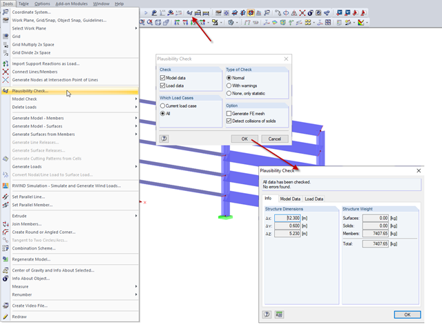
In RFEM and RSTAB, you can check the plausibility of entries before you start the calculation. This is done using "Tools" → "Check Plausibility ..." or the corresponding button in the toolbar. There are three different types of checks available.
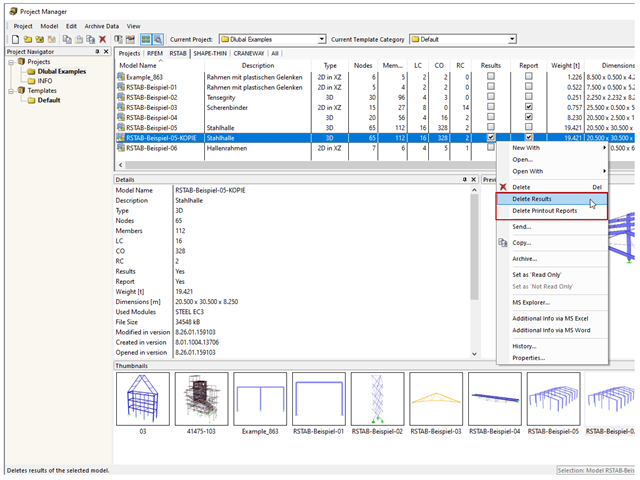
In rare cases, it may happen that an RFEM or RSTAB file cannot be opened. These files contain mostly results and report data.

In RF-/STEEL EC3, sets of members are calculated according to the General Method (EN 1993-1-1, Cl. 6.3.4) together with the stability analysis. To do this, it is necessary to determine the correct support conditions for the equivalent structure with four degrees of freedom. In most 3D models today, you can quickly lose track of the location of a set of members in the system.
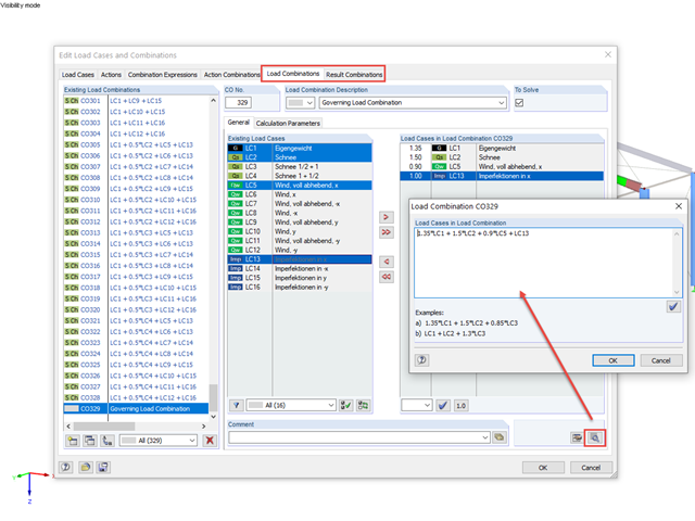
RFEM and RSTAB offer the possibility to edit or check the combinations directly by entering text.
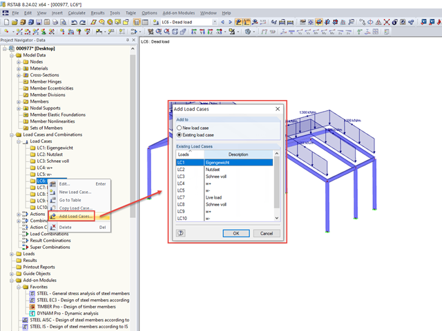
If you want to import a block with previously saved loads into an existing model, the load cases are not integrated into the existing load cases, but are added to the existing ones.
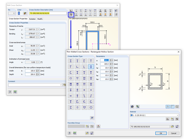
If you define a parametric cross-section in the library using its dimensions, the geometric properties are coded in the cross-section description; for example, "TO 200/100/10/10/10/10".

The reinforced concrete design for fire situations is carried out according to the simplified method based on EN 1992-1-2, Clause 4.2. The "zone method" described in Annex B.2 is used: The cross-section is subdivided into a number of parallel zones of equal thickness, and their temperature-dependent compressive strength is determined. The reduced load-bearing capacity in the event of fire exposure is thus represented by a reduced structural component's cross-section with reduced strengths.

With the "Info About Object..." function available in the menu under "Tools", you can display all the information about an object by placing the cursor on it in the graphical window.
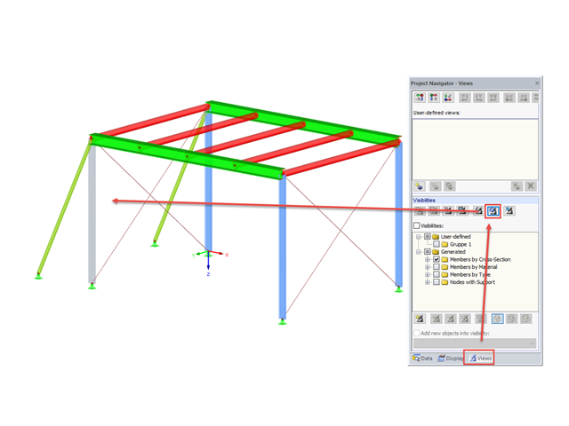
In RFEM and RSTAB, you can apply various visibilities in the Views project navigator.