10 Results
View Results:
Sort by:

The optimal scenario in which punching shear design according to ACI 318-19 [1] or CSA A23.3:19 [2] should be utilized is when a slab is experiencing a high concentration of loading or reaction forces occurring at one single node. In RFEM 6, the node in which punching shear is an issue is referred to as a punching shear node. The causes of these high concentration of forces can be introduced by a column, concentrated force, or nodal support. Connecting walls can also cause these concentrated loads at wall ends, corners, and ends of line loads and supports.

The punching shear design, in line with EN 1992-1-1, should be performed for slabs with a concentrated load or reaction. The node where the design of punching shear resistance is performed (that is, where there is a punching problem) is called a node of punching shear. The concentrated load at these nodes can be introduced by columns, concentrated force, or nodal supports. The end of the linear load introduction on slabs is also regarded as a concentrated load and therefore, the shear resistance at wall ends, wall corners, and ends or corners of line loads and line supports should be controlled as well.
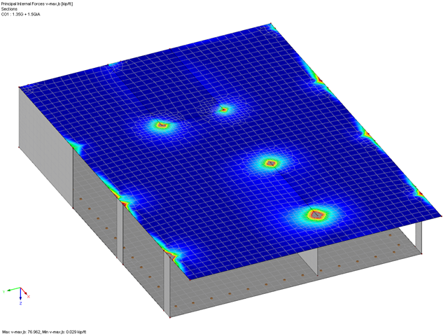
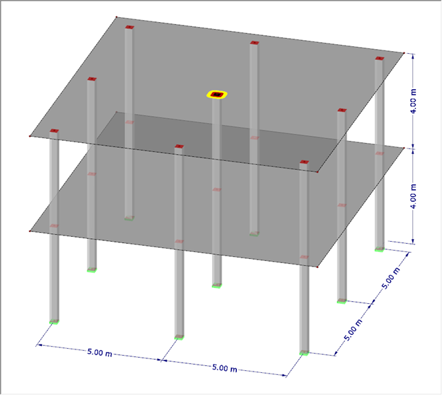
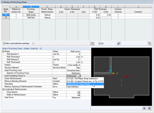
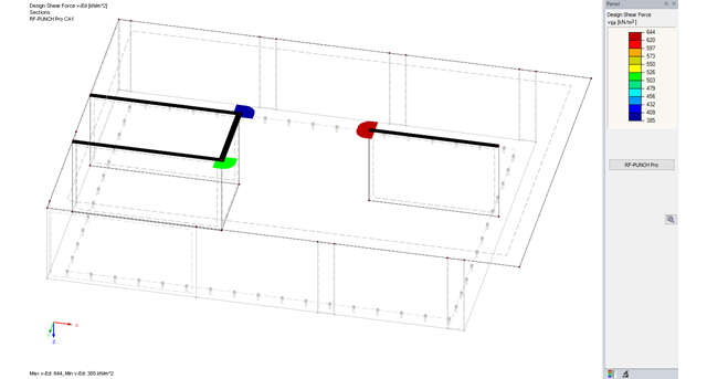
In RF-PUNCH Pro, you can perform the punching shear design on wall corners and wall ends. The basis for the design is the punching load, which is automatically determined from the RFEM internal forces in the connected surface. Since the surface internal forces from the RFEM calculation may be subject to the influence of singularity locations, this can also have a negative influence on the determined punching load at the wall corner or end. This article describes possible optimization options that you can use to minimize this unfavorable influence.

In RF-PUNCH Pro, enlarged column heads can be arranged at point-supported punching shear points, thus increasing the shear force resistance of a reinforced concrete floor. In the following article, we will show the punching shear design with the optional application of an enlarged column head.

RF-PUNCH Pro performs punching shear design on concentrated load application locations (column connection, nodal support, and nodal load) as well as on wall ends and wall corners.
With RF-PUNCH Pro, the punching shear design can be performed according to 6.4, EN 1992-1-1. In the following example, the design according to DIN EN 1992-1-1 will be presented first with automatic design of the inner and outer perimeters and then on the basis of the inner perimeters defined by the user on a simple example.
The RF-PUNCH Pro add-on module allows you to perform punching shear designs according to EN 1992‑1‑1 [1]. In addition to the design checks of single columns, wall ends and wall corners can be analyzed in RF‑PUNCH Pro. At this point, I would also like to reference a previous article about RF‑PUNCH Pro, which explains how to determine punching load on wall ends and wall corners.
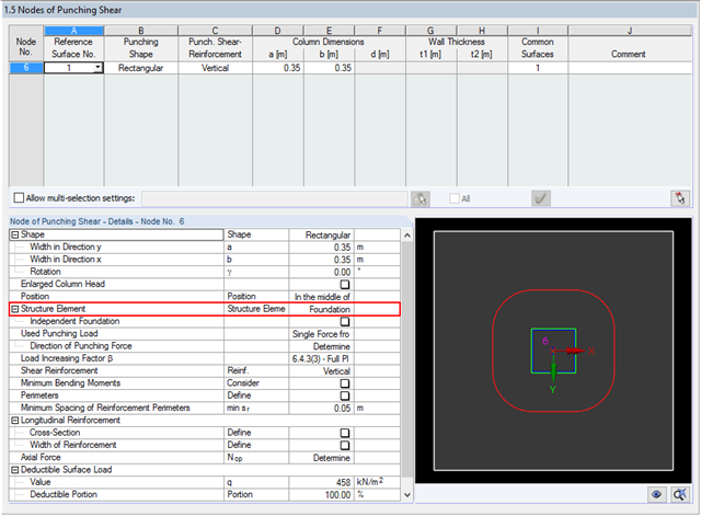
The RF‑PUNCH Pro add‑on module allows you to perform the punching shear design of floor slabs and foundation plates according to EN 1992‑1‑1. In the case of a floor slab, the basic control perimeter is applied according to 6.4.2 (1), EN 1992‑1‑1 [1] at a distance of 2d from the loaded area.

For structural components consisting of slabs, it is necessary to perform shear design on the locations with concentrated load introduction, applying the punching shear design rules according to Sect. 6.4 of EN 1992‑1‑1 [1]. The concentrated load introduction is present on the individual locations; for example, by columns, concentrated load, or nodal supports. In addition, the end of linear load introduction on slabs is also regarded as concentrated load introduction. For example, this includes wall ends, wall corners, and ends or corners of line loads and line supports. You can perform the punching shear design for floor slabs or foundations, considering the existing available plate topology about the designed node of punching shear. The punching shear design according to EN 1992‑1‑1 checks that the acting shear force vEd does not exceed the resistance vRd.
The RF-PUNCH Pro add-on module allows you to perform punching shear design of slabs and foundation plates (floor slabs) on wall ends and wall corners.