
In accordance with DIN 18800, Part 2, the designs are carried out separately for flexural buckling and lateral-torsional buckling to simplify the calculation. Generally, the flexural buckling design is performed in the framework plane using the stress analysis of the planar structure according to the second-order analysis, considering design loads and pre-deformations.
The lateral-torsional buckling design is performed on an individual member detached from the entire structure by using defined boundary conditions and loads in accordance with the elastic-elastic method.
RF-/FE-LTB searches for the governing failure mode by means of the critical load factor which describes flexural, torsional, and lateral-torsional buckling, or the combination of all failure modes, depending on the model and load applied. Then, the module performs recalculation to obtain the required operands.
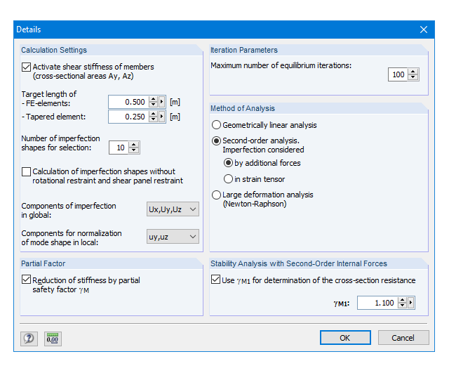
Detail settings control whether the critical load factor is calculated due to loss of stability (providing the material is defined by infinitely elastic properties), or with stress limitation.
If necessary, you can adjust the size of the finite elements. You can also modify the partial safety factor γM. In RF-/FE-LTB, iteration parameters are preset appropriately to calculate all common models, but can be adjusted individually.
Comprehensive and easy options in the individual input windows facilitate the representation of the structural system:
Nodal Supports
- The support type of each node is editable.
- It is possible to define a warp stiffening on each node. The resulting warp spring is determined automatically using the input parameters.
Elastic member foundation
- In the case of elastic member foundations, you can manually enter spring constants.
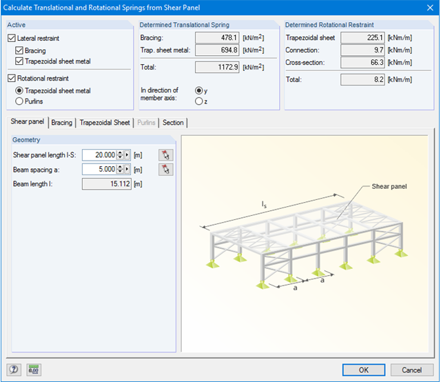
- Alternatively, you can use the various options to define the rotational and translational springs from a shear panel.
Member End Springs
- RF-/FE-LTB calculates the individual spring constants automatically. You can use the dialog boxes and detailed pictures to represent a translational spring by connecting component, a rotational spring by a connecting column, or a warping stiffener (available types: end plate, channel section, angle, connecting column, cantilevered portion).
Member Hinges
- If there are no member hinges defined in RFEM/RSTAB for the set of members, you can define them directly in the RF-/FE-LTB add-on module.
Load Data
- The nodal and member loads of the selected load cases and combinations are displayed in separate windows. There you can edit, delete, or add them individually.
Imperfections
- RF-/FE-LTB automatically applies the imperfections by scaling the lowest eigenvector.
After the calculation, the deformations, internal forces, support forces, and stresses are displayed. Since the module considers warping torsion, the diagrams of the warping bimoment, as well as of the primary and the secondary torsional moment, are also available. Stability analysis uses the imperfections during the calculation and determines the critical load factors that can be used to determine Mki and Nki.
In addition to the result values in tables, the corresponding cross-section graphic is shown. In RFEM/RSTAB, various results are highlighted in different colors on the member model. You can modify the colors and values assigned.
Result diagrams of a set of members provide targeted evaluation. It is also possible to represent all intermediate values. Finally, it is possible to export all tables to MS Excel or in a CSV file. A dialog box includes the necessary export data.

After entering the model in RFEM/RSTAB, it is possible to open the RF-/FE-LTB add-on module. Here you can define continuous members and load cases or combinations to be designed in a design case.
The continuous members can be selected graphically as well. The materials and cross-sections used in RFEM/RSTAB are already preset but can always be adjusted, if necessary. Extensive libraries are available for this purpose.
.png?mw=640&hash=53c64389797699e939283ddbfc3d88485fcbfbf5)
- Full integration in RFEM/RSTAB, including import of all relevant loads
- General stress analysis with warping torsion according to elastic-elastic method
- Stability analysis of planar continuous members for buckling and lateral-torsional buckling
- Determination of critical load factor and thus of Mcr or Ncr (the factor can be used in RF-/LTB for the el/pl design)
- Lateral-torsional buckling analysis of any cross-section (also the SHAPE-THIN cross-sections)
- Design of members and sets of members with applied torsion (for example, crane girder)
- Optional determination of the limit load factor (critical load factor)
- Display of eigenmodes and torsional modes on the rendered cross-section
- Wide range of tools for determining shear panels and rotational restraints (such as corrugated sheets, purlins, bracings)
- Easy determination of discrete springs such as warp springs from end plates or rotational springs from columns
- Graphical selection of load application points on a cross-section (upper chord, centroid, lower chord, or any other point)
- Free arrangement of eccentric nodal and line supports on a cross-section
- Determination of value for inclination or precamber by means of eigenvalue analysis
- Special warping releases applicable for definition of warping conditions on transitions