


2020-07-01
009207
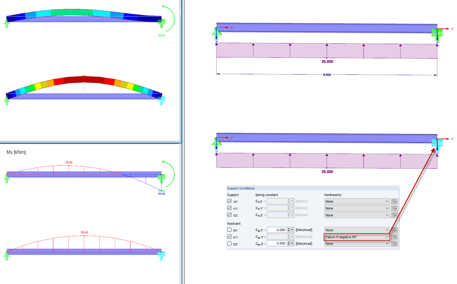
Failure if MY' Negative
Analysis of the negative moments MY' in components for štafety against faiure in technical structures.
The display shows a technical analysis where the failure of structural components at negative moment MY' is analyzed. The graphical display illustrates how negative moments can affect the stability of the structure. The focus is on load optimization and the failure safety of the structural components. Negative moments are emphasized as a critical factor in component failure analysis. This knowledge supports optimization in structural design.
3D Model
Specifications
| Number of Nodes | 2 |
| Number of Lines | 1 |
| Number of Members | 1 |
| Number of Load Cases | 1 |
| Number of Load Combinations | 1 |
| Total Weight | 0,131 t |
| Dimensions (Metric) | 5.058 x 0.117 x 0.117 m |
| Dimensions (Imperial) | 16.59 x 0.38 x 0.38 feet |
| Program Version | 5.24.02 |
2024-05-30
009208
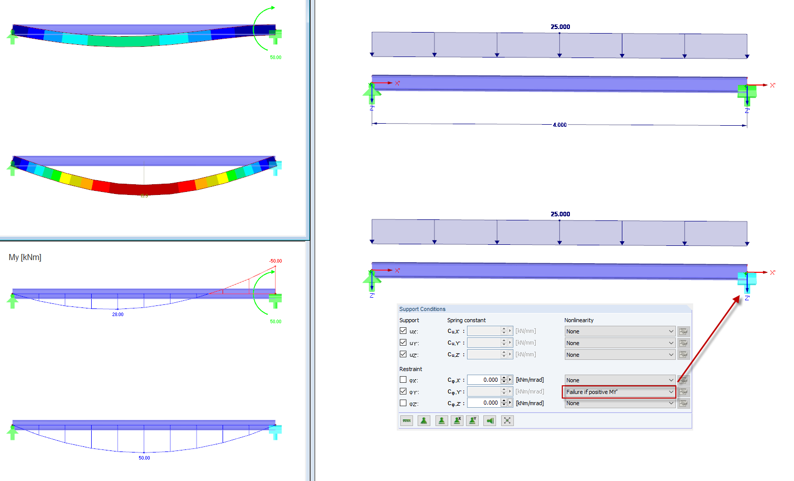
Failure if MY' Positive
3D Model
Specifications
| Number of Nodes | 2 |
| Number of Lines | 1 |
| Number of Members | 1 |
| Number of Load Cases | 1 |
| Number of Load Combinations | 1 |
| Total Weight | 0,131 t |
| Dimensions (Metric) | 5.058 x 0.117 x 0.117 m |
| Dimensions (Imperial) | 16.59 x 0.38 x 0.38 feet |
| Program Version | 5.24.02 |
2020-07-01
009209
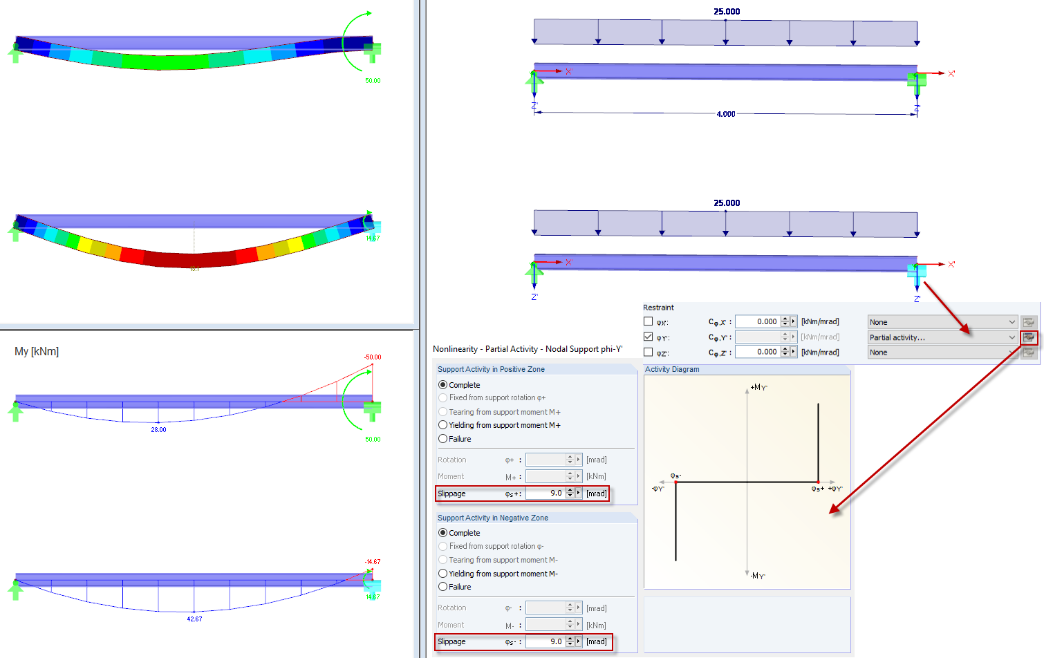
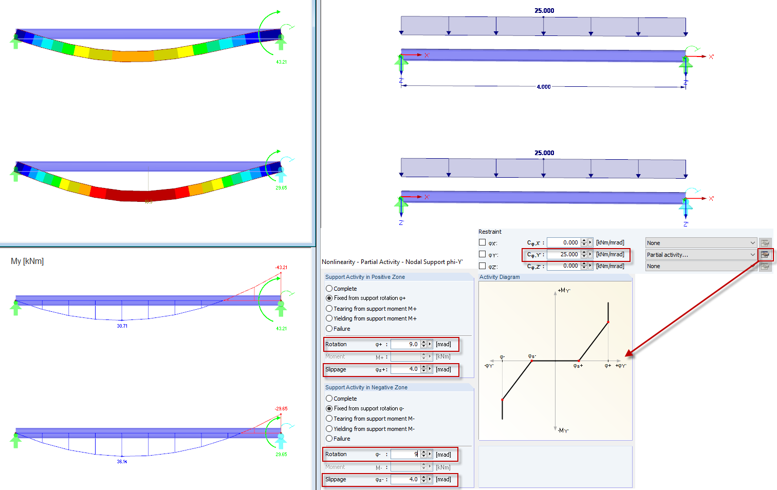
Partial Effect: Slippage
Visualization of movement and slippage between components in a structure. Suitable for simulating mechanical connections.
The image shows a technical display of the slippage between connected structural components within a structure. It illustrates the partial moment behavior at the connection, which is important in understanding the movement or slippage between structural components in mechanical structures. This display can be helpful for the evaluation and optimization of mechanical connections in structural projects.
3D Model
Specifications
| Number of Nodes | 2 |
| Number of Lines | 1 |
| Number of Members | 1 |
| Number of Load Cases | 1 |
| Number of Load Combinations | 1 |
| Total Weight | 0,131 t |
| Dimensions (Metric) | 5.058 x 0.117 x 0.117 m |
| Dimensions (Imperial) | 16.59 x 0.38 x 0.38 feet |
| Program Version | 5.24.02 |
2024-05-30
009210
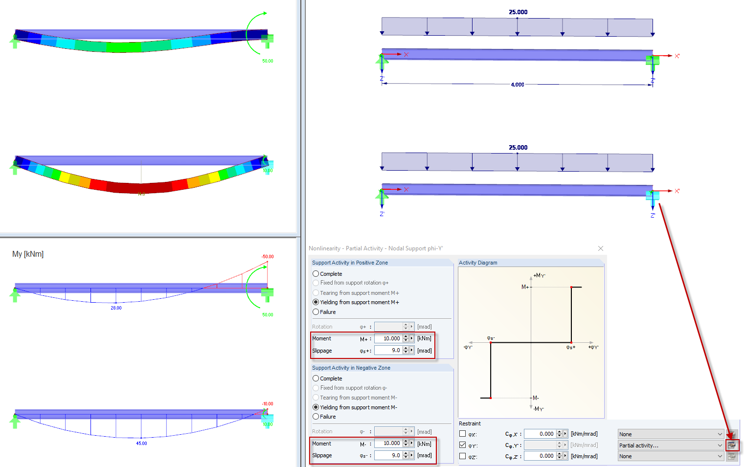
Partial Effect: Yielding and Slippage
3D Model
Specifications
| Number of Nodes | 2 |
| Number of Lines | 1 |
| Number of Members | 1 |
| Number of Load Cases | 1 |
| Number of Load Combinations | 1 |
| Total Weight | 0,131 t |
| Dimensions (Metric) | 5.058 x 0.117 x 0.117 m |
| Dimensions (Imperial) | 16.59 x 0.38 x 0.38 feet |
| Program Version | 5.24.02 |
2024-05-30
009211
Partial Effect: Spring and Slippage
3D Model
Specifications
| Number of Nodes | 2 |
| Number of Lines | 1 |
| Number of Members | 1 |
| Number of Load Cases | 1 |
| Number of Load Combinations | 1 |
| Total Weight | 0,131 t |
| Dimensions (Metric) | 5.058 x 0.117 x 0.117 m |
| Dimensions (Imperial) | 16.59 x 0.38 x 0.38 feet |
| Program Version | 5.24.02 |
2024-05-30
009212
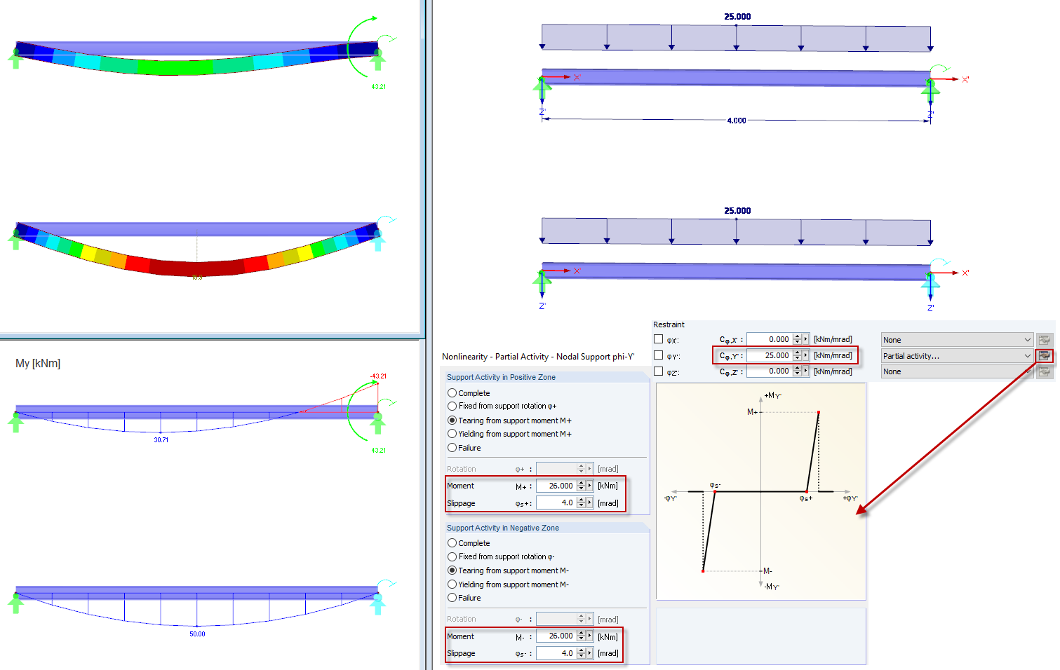
Partial Effect: Tearing from Support Moment
3D Model
Specifications
| Number of Nodes | 2 |
| Number of Lines | 1 |
| Number of Members | 1 |
| Number of Load Cases | 1 |
| Number of Load Combinations | 1 |
| Total Weight | 0,131 t |
| Dimensions (Metric) | 5.058 x 0.117 x 0.117 m |
| Dimensions (Imperial) | 16.59 x 0.38 x 0.38 feet |
| Program Version | 5.24.02 |