.png)
.png?mw=180&hash=e822dfbca83d43855bebb275568227eb1832aa67)


2024-05-30
027077
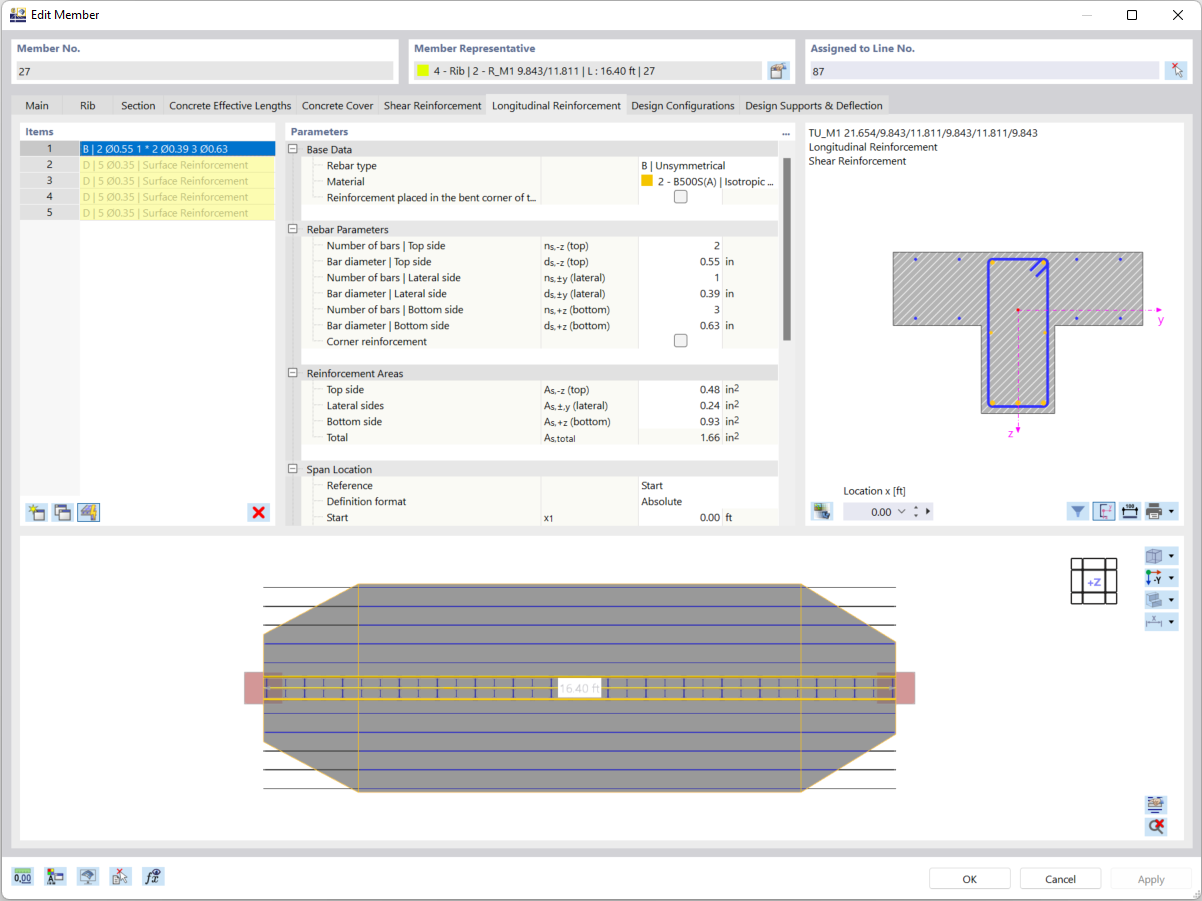
Entering Rib | Definition of Effective Flange Widths by Segment
Individual definition of flange widths of ribbed T-beams by segments. Integration of the surface reinforcement.
The image shows the input options for ribs in the concrete design, where the effective plate width of T-beams can be defined segment by segment. Different widths can be adapted by segmentation in a member, with the option of selecting an incremental or linear transition. In addition, you can specify in the design that the surface reinforcement is integrated as flange reinforcement.
2025-03-26
026975
Individual Definition of Effective Flange Widths of Ribs by Segment
Definition of different flange widths of T-beams for integration in the design of concrete ribs.
In the image, the definition of the effective width of T-beams within a single member is displayed. The different flange widths can be varied segment by segment, and the transition between them can be either stepped or linear. When performing design of reinforced concrete ribs, the defined surface reinforcement is integrated as flange reinforcement.
2024-05-30
020841
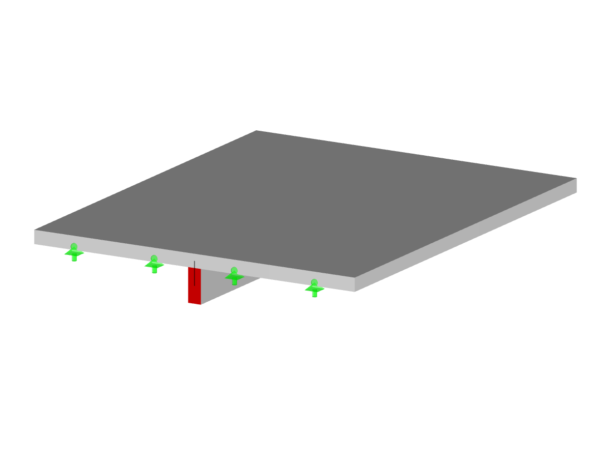
Reinforced Concrete Slab with Rib
Model of a reinforced concrete plate with rib and downstand beam in cracked state II.
The image shows a model of a reinforced concrete slab with an integrated rib, which is displayed in a cracked state II. The downstand beam is clearly visible and illustrates the deformations when subjected to a load. The visual display focuses on the structural stability in the cracked state and provides essential information about the material deformation.
Used in
3D Model
Specifications
| Number of Nodes | 6 |
| Number of Lines | 7 |
| Number of Members | 1 |
| Number of Surfaces | 1 |
| Number of Load Cases | 2 |
| Total Weight | 16.500 t |
| Dimensions (Metric) | 6.000 x 5.000 x 0.350 m |
| Dimensions (Imperial) | 19.69 x 16.4 x 1.15 feet |
| Program Version | 5.25.01 |