


2022-01-05
027616
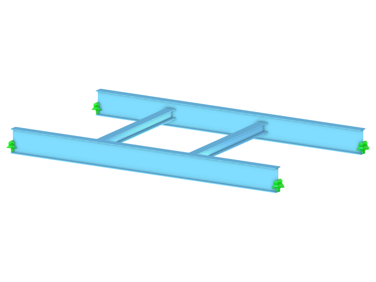
Rod Warping Torsion with Resulting Deformation
Deformation analysis of a rod subjected to warping torsion loads, showcasing the resulting structural behavior.
The image shows a detailed analysis of a rod experiencing warping torsion. The calculation displays the deformation results, illustrating the structural response to applied loads. The model demonstrates how torsion affects the rod's geometry, providing insight into potential performance adjustments.
3D Model
Specifications
| Number of Nodes | 8 |
| Number of Lines | 4 |
| Number of Members | 4 |
| Number of Surfaces | 0 |
| Number of Solids | 0 |
| Number of Load Cases | 2 |
| Number of Load Combinations | 6 |
| Number of Result Combinations | 0 |
| Total Weight | 2.429 tons |
| Dimensions (Metric) | 7,200 x 0,000 x 4,000 m |
| Dimensions (Imperial) | 23.62 x 0 x 13.12 feet |
2024-05-30
022945
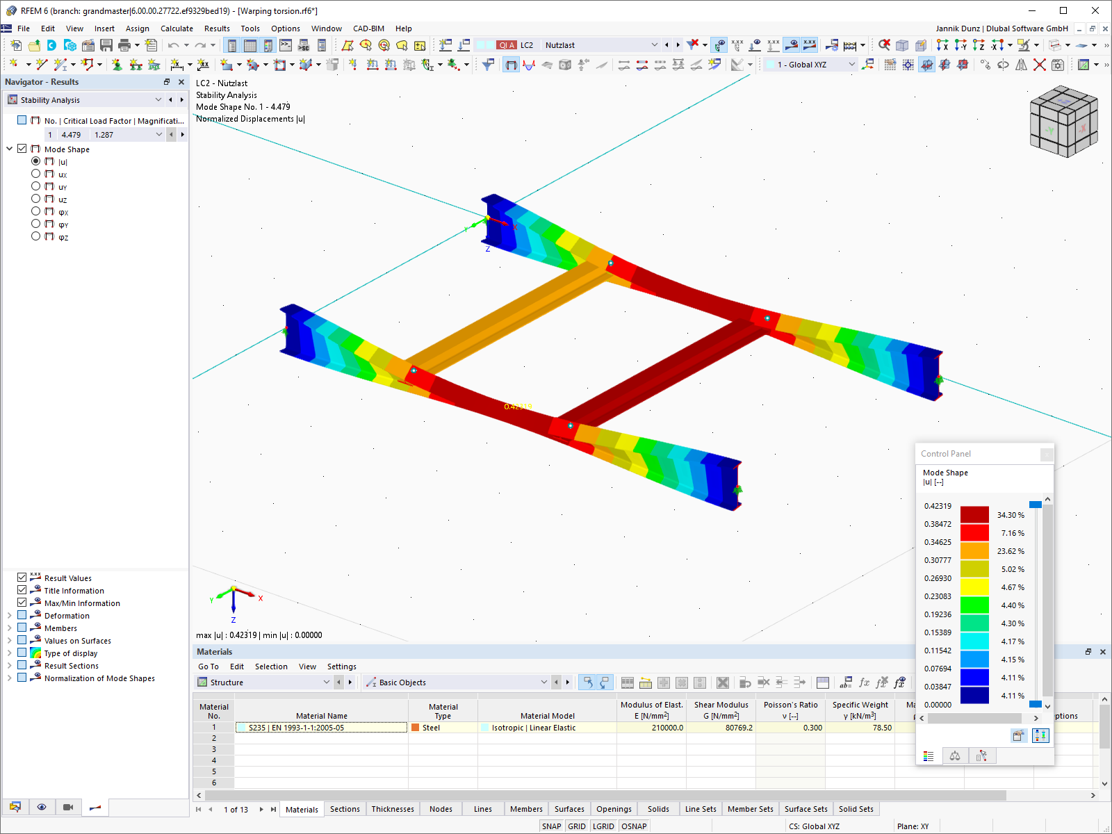
Mode Shape of Entire Model for Lateral-Torsional Buckling
Display of a mode shape for the analysis of lateral-torsional buckling.
The display shows the mode shape of a structural model for the analysis of lateral-torsional buckling. The model visualizes the deformation patterns that occur under load. The calculation of lateral-torsional buckling behavior is crucial for the stability of structures and helps to avoid design errors. The analysis of the mode shapes provides deeper insights into possible weak points and optimization potential.
3D Model
Specifications
| Number of Nodes | 8 |
| Number of Lines | 4 |
| Number of Members | 4 |
| Number of Surfaces | 0 |
| Number of Solids | 0 |
| Number of Load Cases | 2 |
| Number of Load Combinations | 6 |
| Number of Result Combinations | 0 |
| Total Weight | 2.429 tons |
| Dimensions (Metric) | 7,200 x 0,000 x 4,000 m |
| Dimensions (Imperial) | 23.62 x 0 x 13.12 feet |
2025-03-29
022942
Warping Moment Distribution
Display of a warping moment in Steel Design
The image shows the distribution of the warping moment in a steel structure that takes into account internal forces from the calculation with warping torsion and seven degrees of freedom. This analysis is useful for the precise design of structural steel elements. The detailed display allows engineers to fully understand the deformation and stress distribution in structures.
3D Model
Specifications
| Number of Nodes | 8 |
| Number of Lines | 4 |
| Number of Members | 4 |
| Number of Surfaces | 0 |
| Number of Solids | 0 |
| Number of Load Cases | 2 |
| Number of Load Combinations | 6 |
| Number of Result Combinations | 0 |
| Total Weight | 2.429 tons |
| Dimensions (Metric) | 7,200 x 0,000 x 4,000 m |
| Dimensions (Imperial) | 23.62 x 0 x 13.12 feet |
2024-05-30
022943
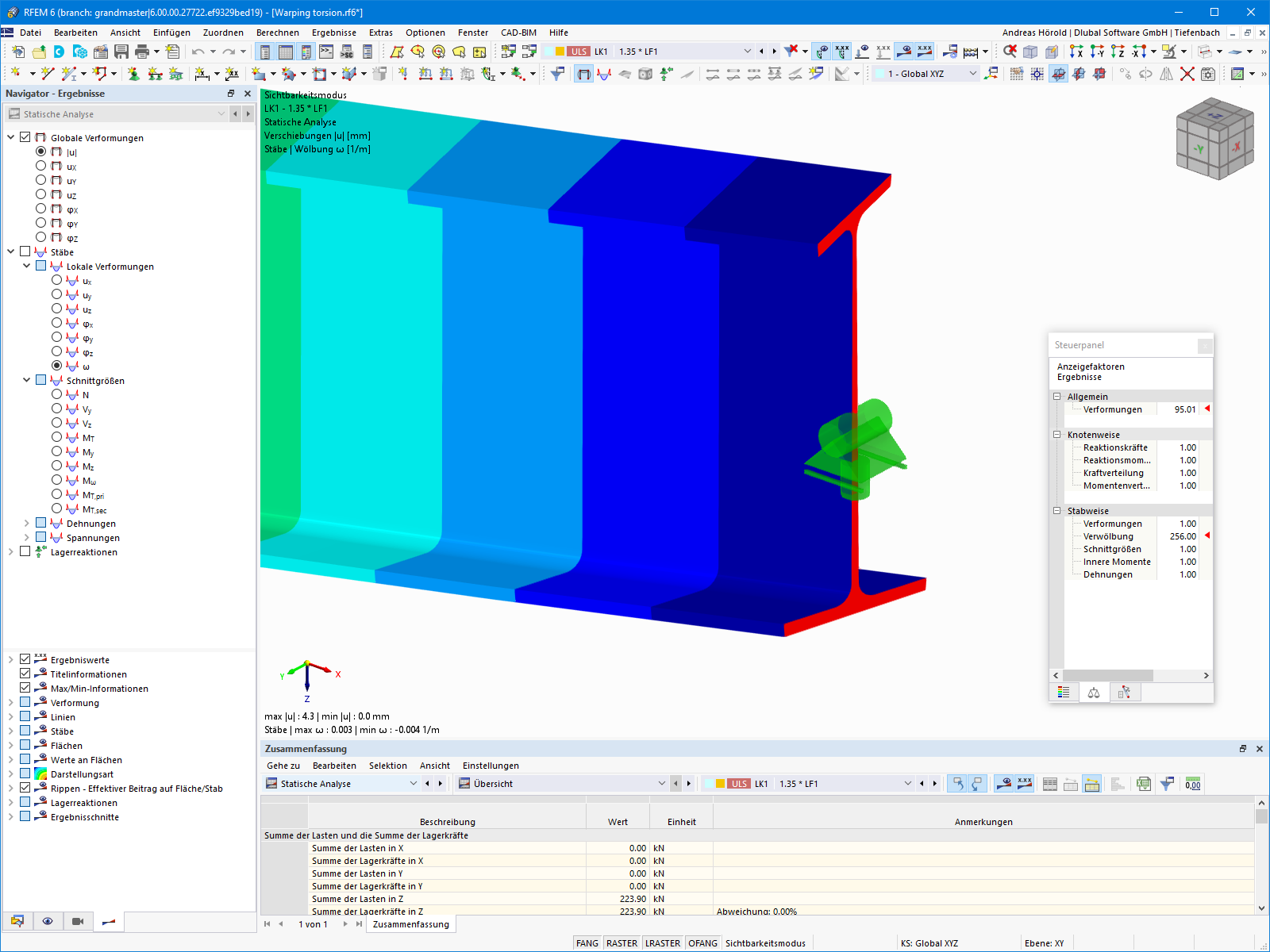
Cross-Section Warping
Section warping and consideration of internal forces in steel design due to the warping torsion
The image shows the process of cross-section warping in steel design, in which the internal forces resulting from the calculation with Warping Torsion are taken into account. This method allows for a detailed analysis of the relative torsion across the cross-section. The method utilizes advanced features for the calculation of warping force and moment distribution, resulting in precise and efficient structural design.
3D Model
Specifications
| Number of Nodes | 8 |
| Number of Lines | 4 |
| Number of Members | 4 |
| Number of Surfaces | 0 |
| Number of Solids | 0 |
| Number of Load Cases | 2 |
| Number of Load Combinations | 6 |
| Number of Result Combinations | 0 |
| Total Weight | 2.429 tons |
| Dimensions (Metric) | 7,200 x 0,000 x 4,000 m |
| Dimensions (Imperial) | 23.62 x 0 x 13.12 feet |
2025-03-29
025633
Member Warping Torsion
Advanced Warping Torsion Assessment for Steel Structures
The content revolves around the advanced computation of member warping torsion, highlighting the integration of seven degrees of freedom in the analysis of steel structures. This feature is employed in RFEM and RSTAB to consider cross-sectional warping, enabling precise calculation of internal forces like axial force (N), primary and secondary torsional moments (Mt,pri, Mt,sec), and warping moment (Mω). Such detailed assessment allows for enhanced accuracy in steel structure design.
Used in
3D Model
Specifications
| Number of Nodes | 8 |
| Number of Lines | 4 |
| Number of Members | 4 |
| Number of Surfaces | 0 |
| Number of Solids | 0 |
| Number of Load Cases | 2 |
| Number of Load Combinations | 6 |
| Number of Result Combinations | 0 |
| Total Weight | 2.429 tons |
| Dimensions (Metric) | 7,200 x 0,000 x 4,000 m |
| Dimensions (Imperial) | 23.62 x 0 x 13.12 feet |
2024-05-30
030199
Crane Runway Girder | Torsional Warping (7 DOF) in RFEM 6
Crane Runway Girder | Warping Torsion Animation
3D Model
Specifications
| Number of Nodes | 3 |
| Number of Lines | 1 |
| Number of Members | 1 |
| Number of Surfaces | 0 |
| Number of Solids | 0 |
| Number of Load Cases | 9 |
| Number of Load Combinations | 18 |
| Number of Result Combinations | 0 |
| Total Weight | 1,405 t |
| Dimensions (Metric) | 12,000 x 0,000 x 0,000 m |
| Dimensions (Imperial) | 39.37 x 0 x 0 feet |