


2024-05-30
038957
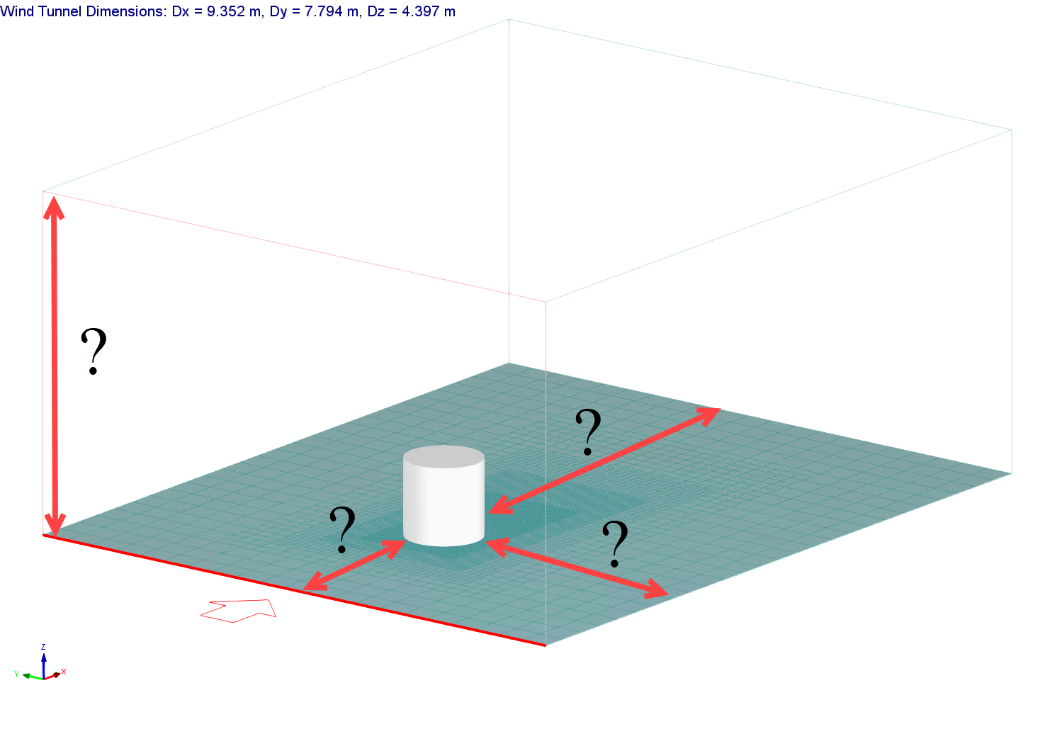
Image 1: Wind Tunnel Dimensions
2024-05-30
038959
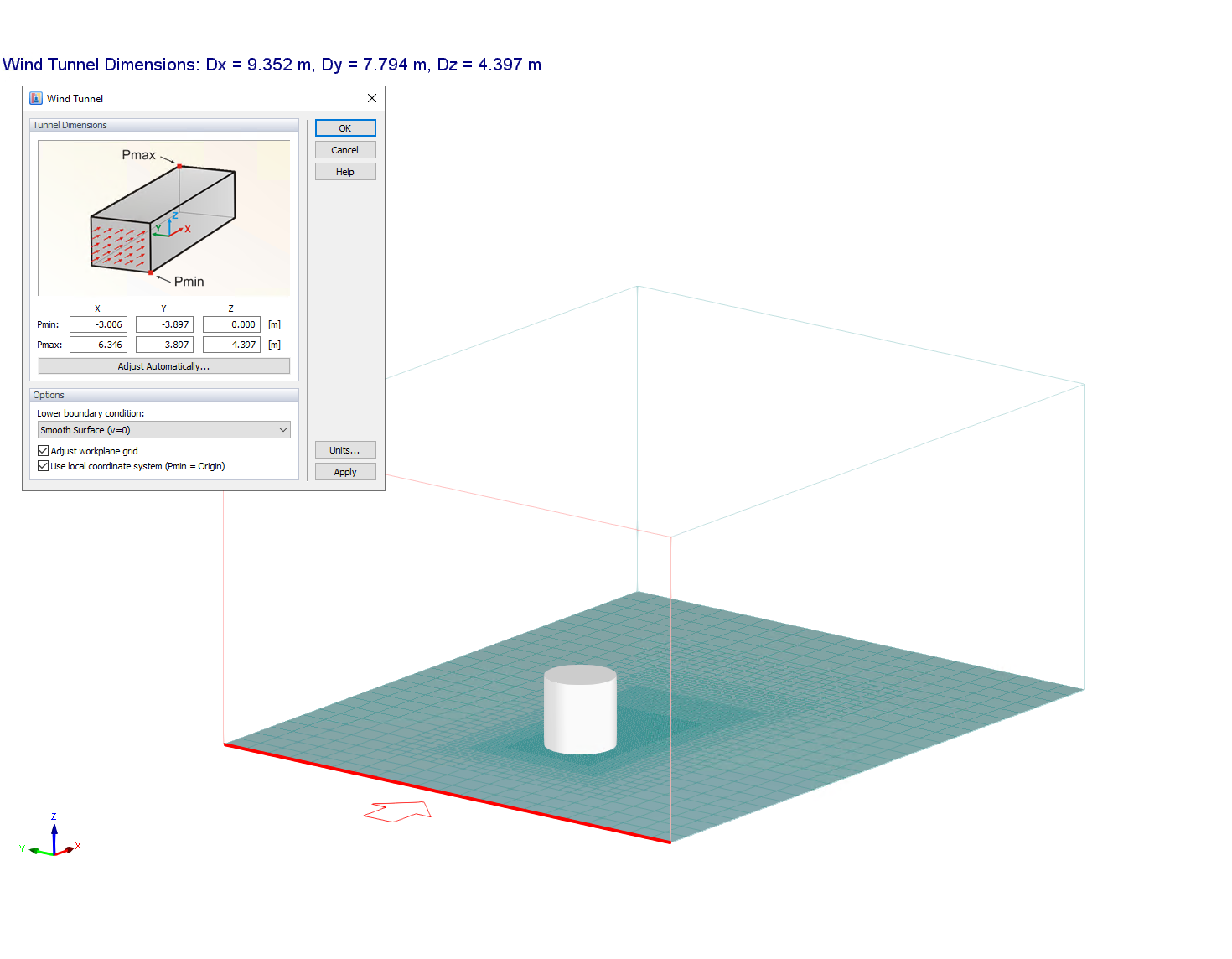
Image 2: Default Wind Tunnel Dimensions
2024-05-30
038958
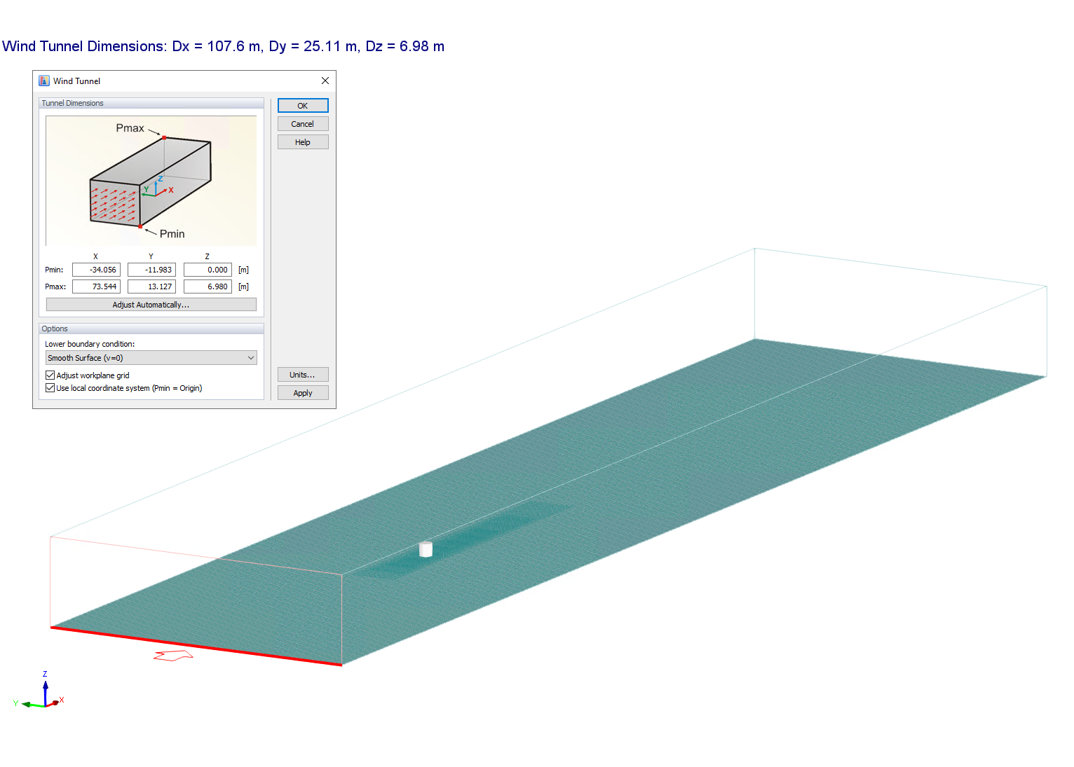
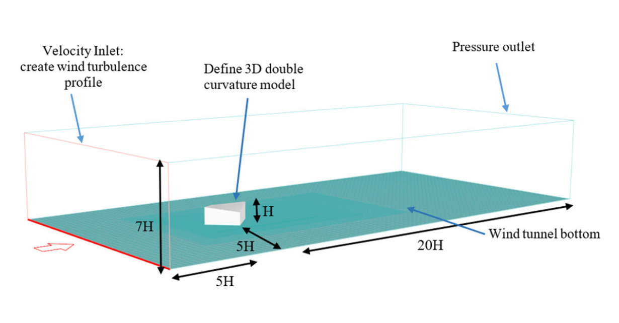
Image 3: Recommended Wind Tunnel Dimensions
2024-05-30
038960
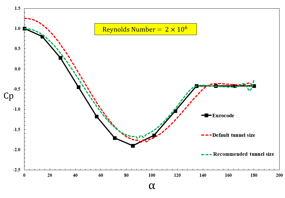
Image 4: Cp Value of Cylinder Center Line for Both Default and Recommended Wind Tunnel Size
2024-05-30
038961
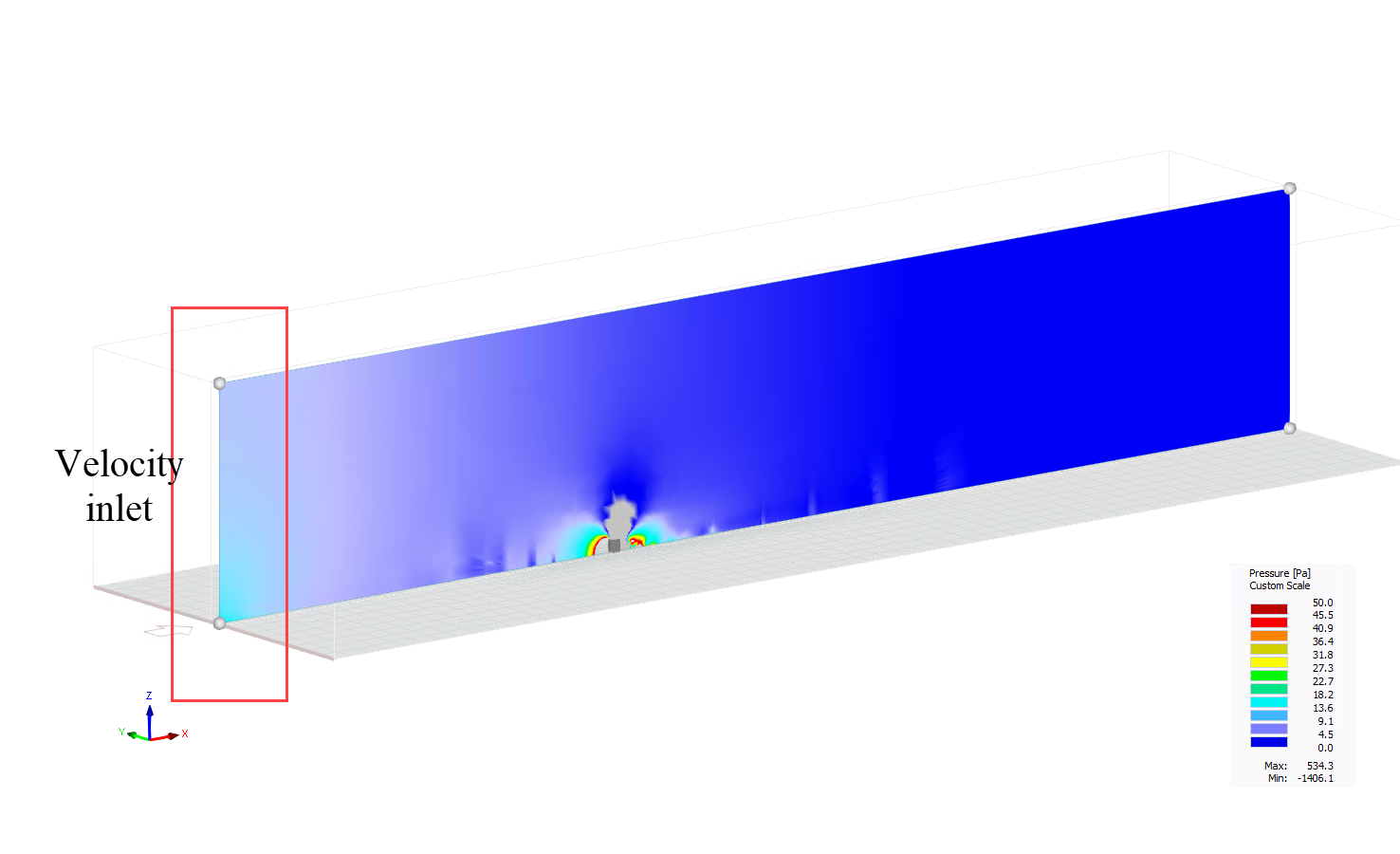
Image 5: Pressure Field Near Velocity Inlet
2024-05-30
038963
Image 6: Schematic Dimensions for Recommended Wind Tunnel Size in General Aerodynamic Application