In recent years, there has been a rise in interest in using computational fluid dynamics, known as CFD, to design wind-susceptible structures. This is due to the fact that advancements in computer power have made the solution to complicated flow problems relatively inexpensive. The size of the computational domain is an important aspect that has a significant impact on the accuracy as well as the cost of CFD simulations.
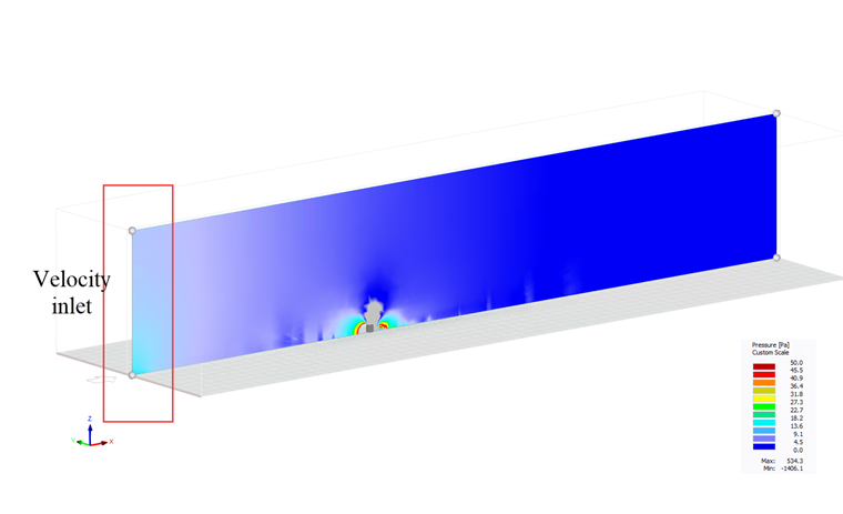
The fundamental flow equations are discretized and solved in a volumetric area outside the building model, which is referred to as the computational domain (Image 1). The limits of a typical cuboid domain have a total of six boundaries. These borders, with the exception of the domain's bottom, are essentially non-physical; therefore, their effects on the flow area are a source of simulation error (hereby termed domain errors). It is important to set non-physical barriers far enough away from the structure to minimize major effects on the results. The model's computational cost might rise if the borders are positioned too far out. The size of the computational domain must be optimized with both computational cost and solution accuracy in mind [1].
Computational wind engineering (CWE) best practice recommendations [2] [3] acknowledges the significance of a computational domain with an appropriate size for solution accuracy. These recommendations link domain mistakes to problems with wind tunnel testing that are similar, such as blockage effects in domains with limited cross-sectional areas and artificial acceleration of local flow in domains with insufficient space between the domain boundaries and the building model. Hence, the minimum distance between the domain borders and the building model and the maximum blockage ratios, or a combination of the two, is used to specify the size requirements [3].
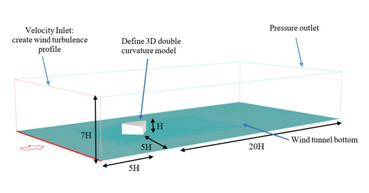
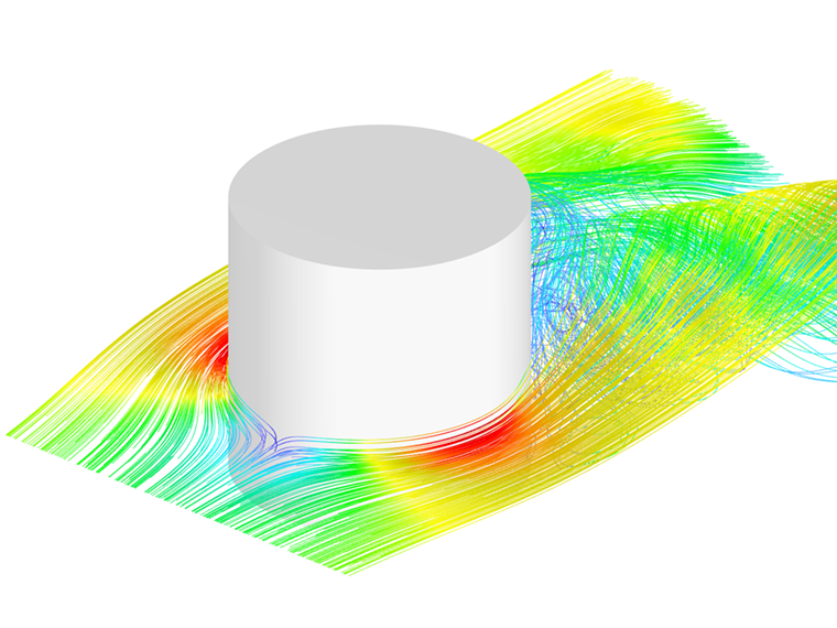
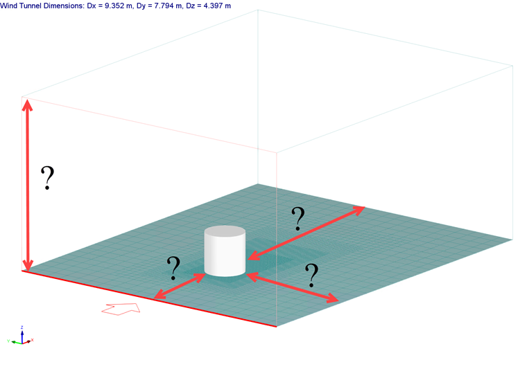
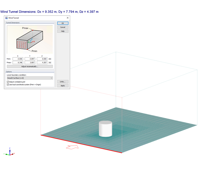
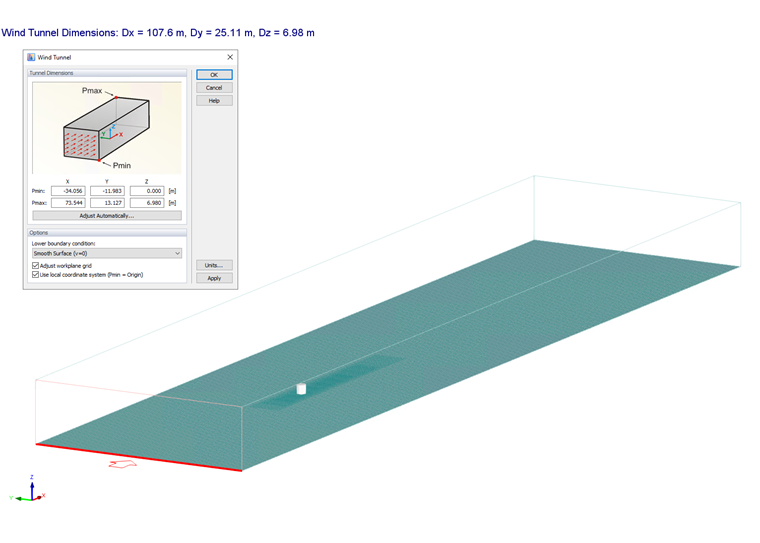
Here there is an example of the Eurocode cylinder shape [4] in which two different computational domain dimensions are considered. The first case (Image 2) is the default setting of RWIND, which is a less accurate but faster calculation, and the second is the recommended wind tunnel size (Image 3) which is more accurate but also has a more computational cost. For example, for the default wind tunnel size, 23 minutes is needed to complete the CFD simulation, while for the recommended wind tunnel size, 42 minutes is required in order to finish the simulation (~80% increase of the computational cost). Also, it is important to note the simulation was performed by CPU: Intel(R) Xeon(R) Gold 6248R CPU @ 3.00GHz and 128 GB RAM for 1000 iterations.
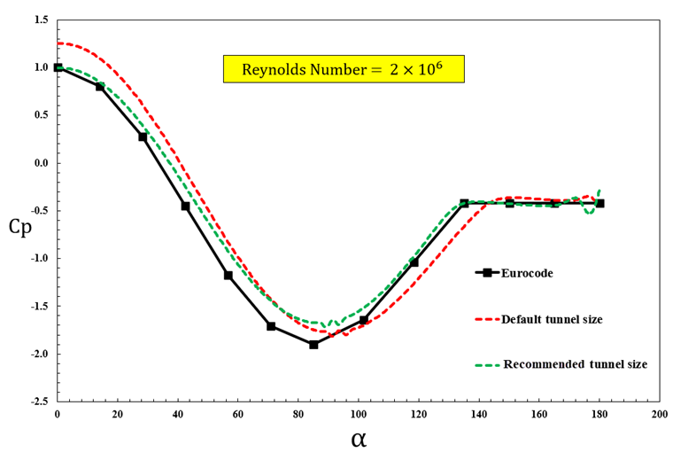
The wind pressure coefficient (Cp) diagram (Image 4) shows that the size of the computational domain can play an important role in the level of accuracy of the results, especially for the positive pressure area. The schematic recommended wind tunnel size in aerodynamics is shown in Image 6 [5]. The critical point is to pay attention to the values of the pressure field near the velocity inlet; they should be optimally close to zero (Image 5).