Selecting the Anisotropic material model | Damage for concrete in the software interface
Material model Anisotropy | Damage | Diagram definition and parameters | Concrete, Parameters
Diagram of the concrete material model with anisotropic damage definition | Strength parameters
Concrete material model with anisotropic damage approach | Stress-strain diagram
2025-01-07
054797
  • RFEM 6
  • RSTAB 9
  • Concrete Design for RFEM 6
    • Concrete Design for RSTAB 9
    • Nonlinear Material Behavior for RFEM 6
    • Concrete Structures
    • Structural Analysis & Design
    • Finite Element Analysis
    • Nonlinear Analysis
    • Eurocode 2

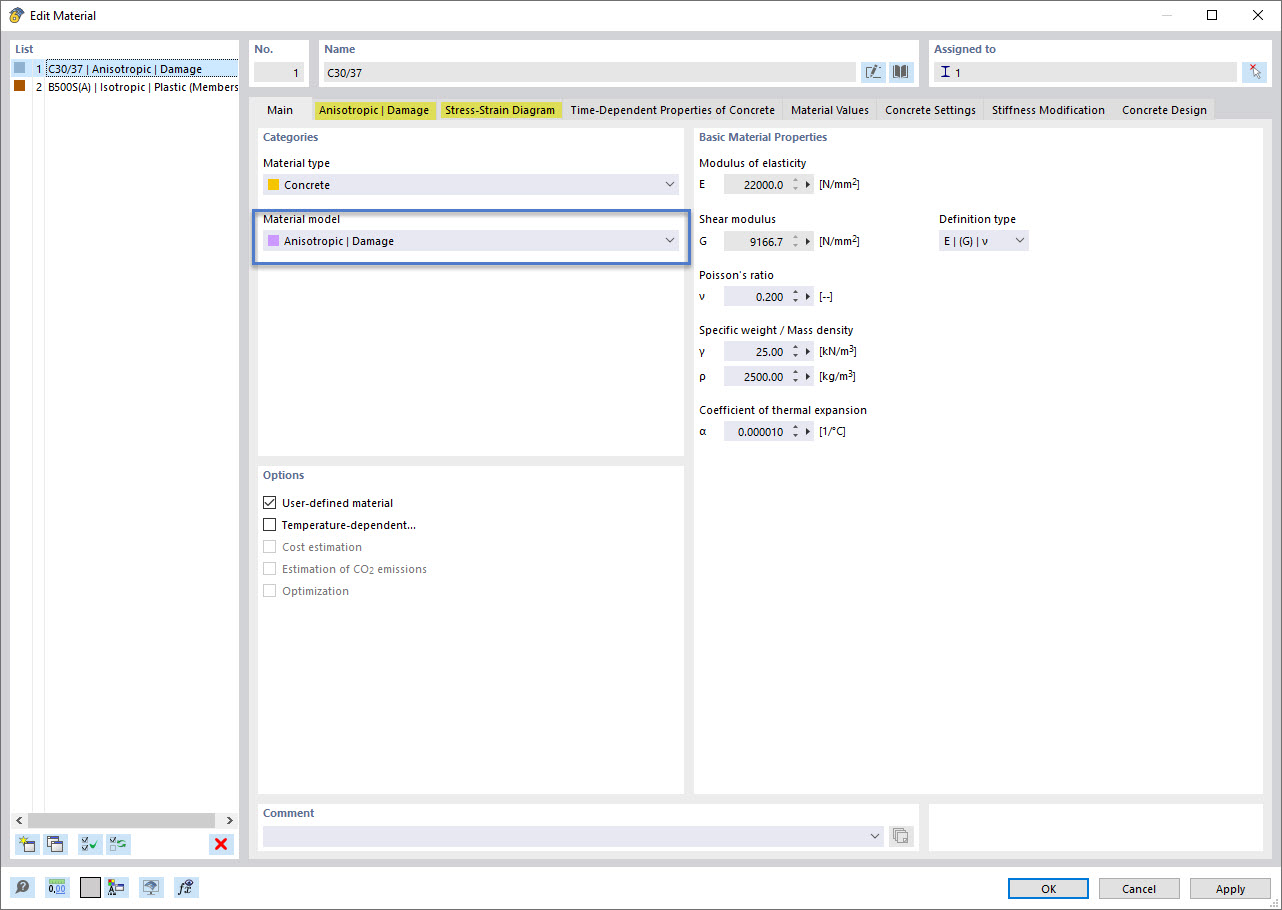
Material Model Anisotropic | Damage – Image 1/4: Assigning Material Model

Selecting the Anisotropic material model | Damage for concrete in the software interface

The image shows a software interface for assigning the material model “Anisotropic | Damage” for concrete. The selection process is displayed, with the specific parameters of the concrete material being set. The user guidance for linking the material to the model can be seen.
  • Material model anisotropic
  • Damage
  • Concrete material
  • Select material model
  • Assign material model
Used in
  • Nonlinear Reinforced Concrete Analysis – General Method for Stability Analysis According to DIN EN 1992-1-1
Share
2025-01-07
054796
  • RFEM 6
  • RSTAB 9
  • Concrete Design for RFEM 6
    • Concrete Design for RSTAB 9
    • Nonlinear Material Behavior for RFEM 6
    • Concrete Structures
    • Structural Analysis & Design
    • Finite Element Analysis
    • Nonlinear Analysis
    • Eurocode 2
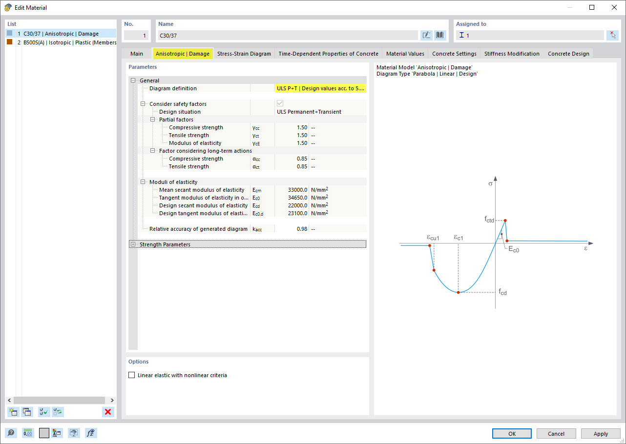
Material Model Anisotropic | Damage - Image 2/4: Diagram Definition and General Parameters
Material model Anisotropy | Damage | Diagram definition and parameters | Concrete, Parameters

The diagram illustrates the input parameters of an anisotropic material model for concrete that takes damage mechanisms into account. It shows axis labels, parameter specifications, and properties for defining the material properties.
  • Material model anisotropic
  • Damage diagram
  • General parameters
  • Concrete material
  • Diagram definition
  • Material parameters
Used in
  • Nonlinear Reinforced Concrete Analysis – General Method for Stability Analysis According to DIN EN 1992-1-1
Share
2025-01-07
054798
  • RFEM 6
  • RSTAB 9
  • Concrete Design for RFEM 6
    • Concrete Design for RSTAB 9
    • Nonlinear Material Behavior for RFEM 6
    • Concrete Structures
    • Structural Analysis & Design
    • Finite Element Analysis
    • Nonlinear Analysis
    • Eurocode 2
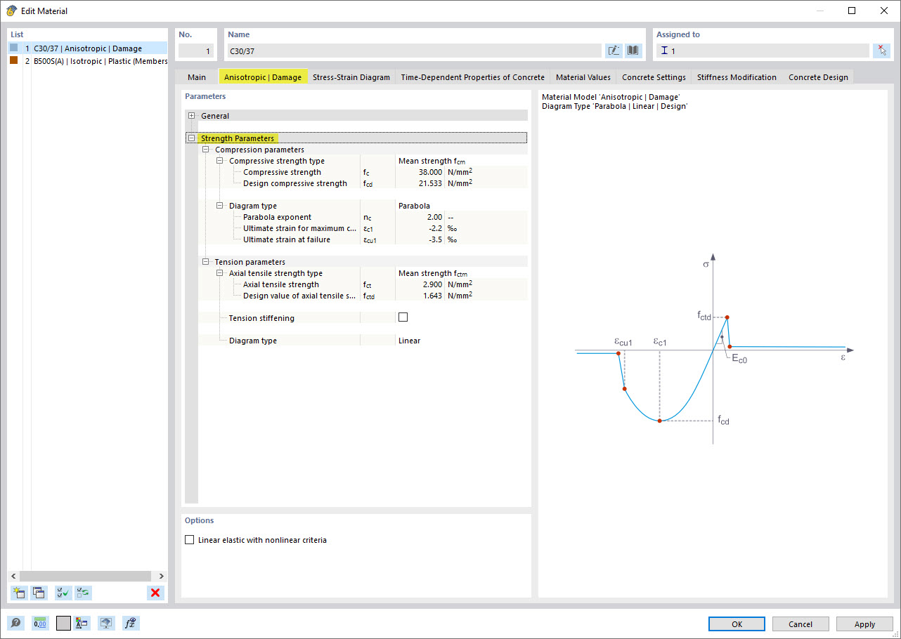
Material Model Anisotropic | Damage - Image 3/4: Definition of Strength Parameters
Diagram of the concrete material model with anisotropic damage definition | Strength parameters

The diagram shows the definition of strength parameters in the concrete material model “Anisotropic | Damage.” Material properties and parameters describing anisotropic behavior and damage mechanisms are displayed. The visualization supports the precise recording of strength limits and material properties.
  • Concrete material model
  • Anisotropic material model
  • Definition of strength parameters
  • Anisotropic damage
  • Resistance parameter diagram
Used in
  • Nonlinear Reinforced Concrete Analysis – General Method for Stability Analysis According to DIN EN 1992-1-1
Share
2025-01-07
054799
  • RFEM 6
  • RSTAB 9
  • Concrete Design for RFEM 6
    • Concrete Design for RSTAB 9
    • Nonlinear Material Behavior for RFEM 6
    • Concrete Structures
    • Structural Analysis & Design
    • Finite Element Analysis
    • Nonlinear Analysis
    • Eurocode 2
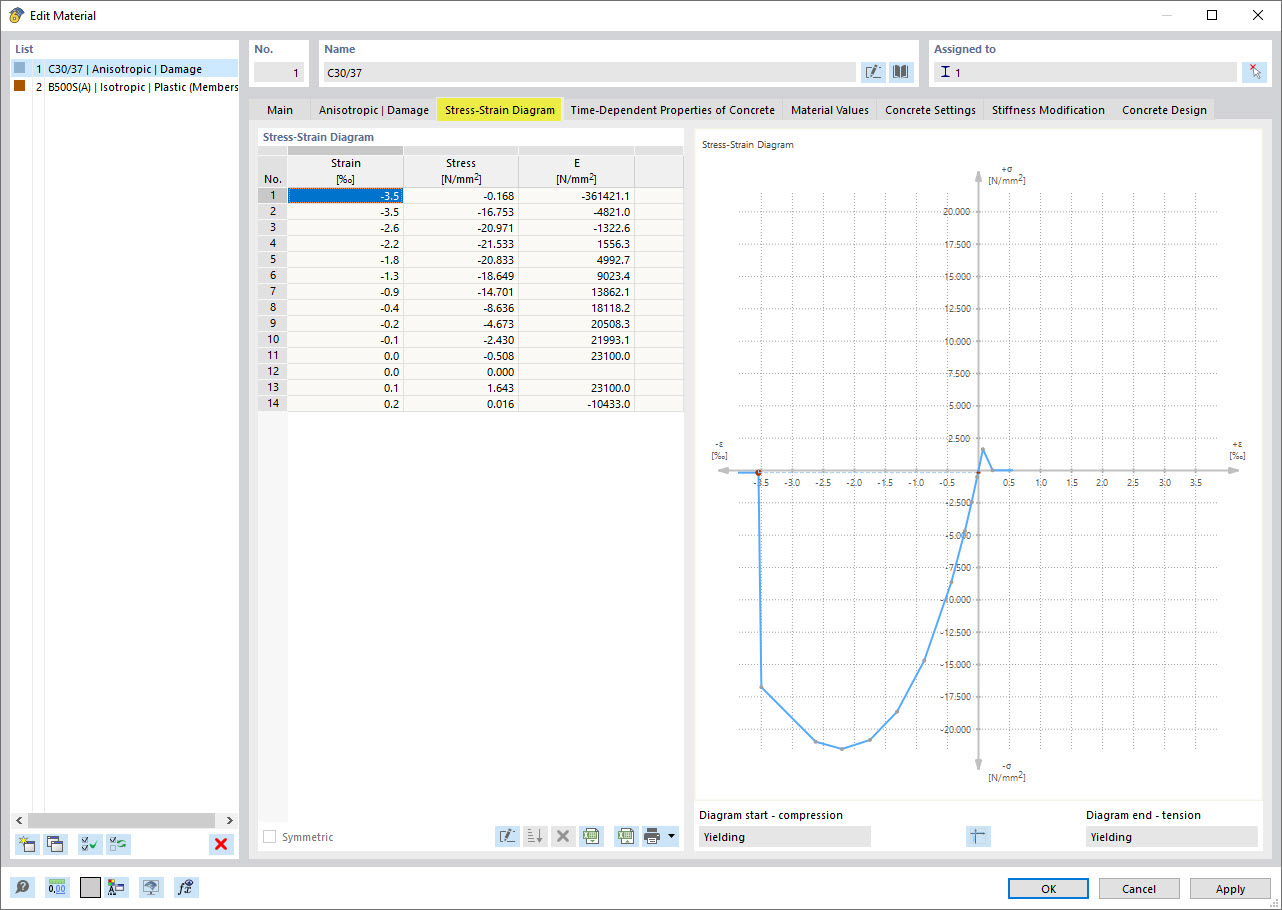
Material Model Anisotropic | Damage - Image 4/4: Resulting Stress-Strain Diagram
Concrete material model with anisotropic damage approach | Stress-strain diagram

The diagram illustrates the stress-strain behavior of a concrete material model with an anisotropic damage approach. It shows the relationship between applied stresses and resulting strains. The graph highlights the effects of material damage on mechanical properties.
  • Anisotropic material model
  • Concrete material model
  • Damage mechanism
  • Stress-strain diagram
  • Anisotropic properties
Used in
  • Nonlinear Reinforced Concrete Analysis – General Method for Stability Analysis According to DIN EN 1992-1-1
Share